


Other Parts Discussed in Thread: SM72295
Hi:
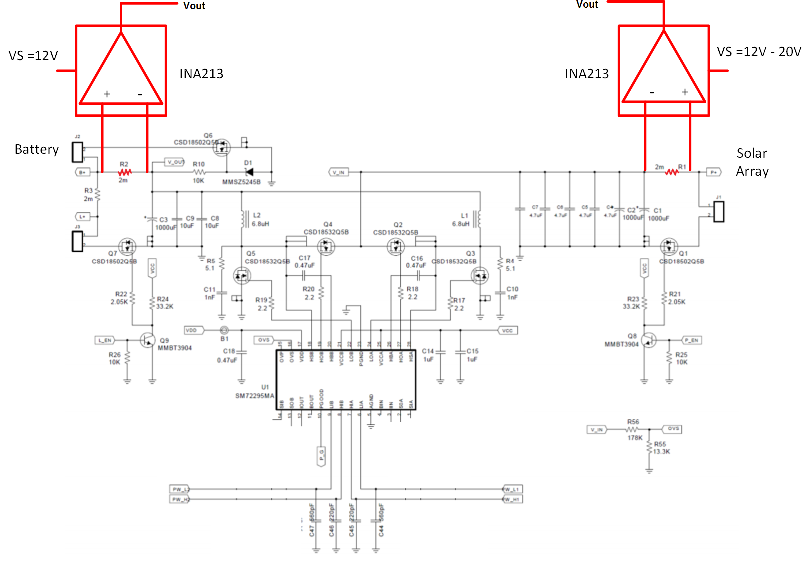
We are using 2 of these devices in an MPPT battery charging circuit, one to measure battery current and the other to measure solar array current. The charger design is based on the TI PMP7605 reference design. We are using a 0.002 ohm sense resistor wired straight across the inputs on the high side of the bridge. The sense resistors are located exactly as they are in the reference design... we are using the INA213's in place of the current sense amps that are integrated with the SM72295.
What I am seeing is that the measured battery charge current is always within 5% of actual but the measured current from the solar array has an error that increases with increasing voltage across the solar array. For a given battery voltage (Vb), I can vary the duty cycle of the switching MOSFETs to vary the voltage that appears across the solar array connector (Vs) from Vb up to about 20v (and beyond if I wanted to but I am aware that the absolute maximum is 26v for the INA213 part). For Vs equal to, or slightly greater than Vb (around 12v), the measured solar array current is OK. As I increase Vs towards the 20v limit however, the measurement error increases to give me increasingly higher solar array currents with errors > 30% of the actual current through the sense resistor. It seems as if I am seeing some kind of gain error that increases with increasing Vcm or perhaps my input bias current is increasing with Vcm?
Thanks for the help


