This thread has been locked.

If you have a related question, please click the "Ask a related question" button in the top right corner. The newly created question will be automatically linked to this question.

INA233: Monitoring voltages >36V with INA233

Part Number: INA233

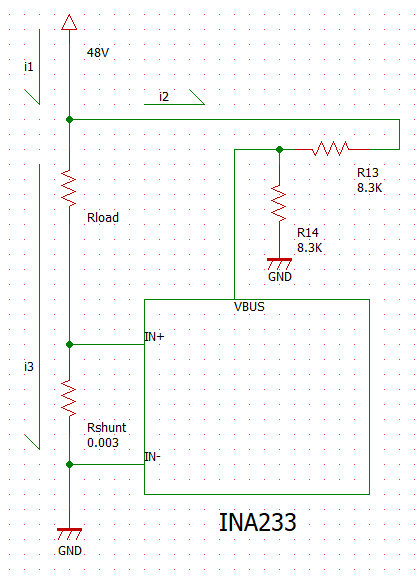
I'd like to use the INA233 to monitor the current and voltage of 48V motor. I understand that the maximum voltage input on the VBUS pin is 36V.

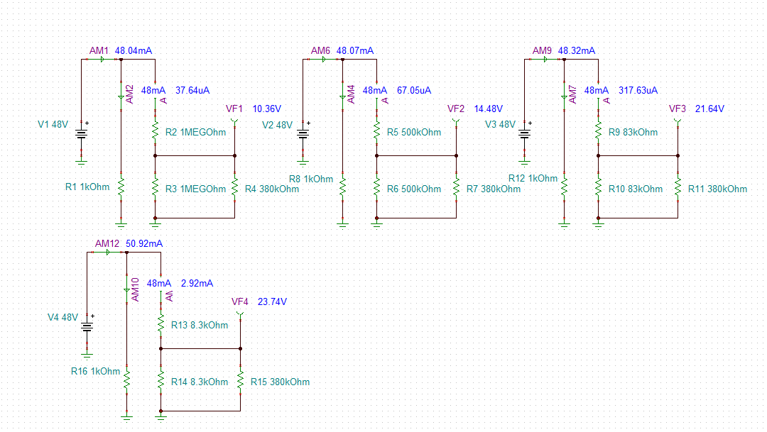
My intention is to add a voltage divider to reduce the input by a factor of 2, such that VBUS will be at a maximum of 24V for my full scale (48V) input. I can see that this will impact the INA233's power calculations, though for my application I am only interested in voltage and current measurements and I can correct the voltage measurement in software to account for the voltage divider.

Does this seem like a valid approach or could there be some other factors that need consideration?

  • Hello Charma56,

    Thanks for considering to use Texas Instruments in your design.  You could use this approach, but you should be aware that this method will introduce errors that can make your measurements deviate substantially from what you might expect. Are you using a high side or low side implementation?  For high-side you will need to consider errors from the divider leading to the input pins (IN+ and IN-) as well as the divider leading to the VBUS pin.  Typically we do not recommend anything besides a filter between the shunt resistor and the power monitor device, and we recommend that the filter have sub 10 ohm resistors.  The reason is that those resistors can dramatically increase error due to gain and error from the device input bias current.

    For the VBUS pin, both implementations can be affected if the lower leg resistor in the divider is too large.  The VBus input impedance is 830kohm and is not trimmed, so it can have potentially a large deviation.  If your divider's lower resistor that is in parallel with this VBus impedance is too high, it could make your bus voltage appear much lower than it really is.  So with this I recommend you use a divider with resistors as low as you can tolerate and performing an initial calibration at startup.

  • Thank you for clarifying. This would be a low side implementation.

    To make sure I understand, if I follow TI's recommended circuit for the shunt resistor connection and only add a voltage divider to the VBUS pin, taking care to keep the resistance as low as possible, there could still be substantial errors in the measurements?

    Specifically could I assume that the current measurement would be unaffected (remaining accurate) and only the voltage measurement would be subject to errors?
  • Hello Charma56,

    You will have bus voltage errors and if you are trying to measure all of the current sourced from the bus, you could potentially have a substantial current measurement error.  Below I illustrate the point.  For my scenario, I assumed the load is 1k ohm for the line you are measuring.  For large divider resistors (1Meg ohm), the current through the shunt line is only a little smaller than all of the current sourced from your bus supply, while the voltage seen at the device VBUS pin is nearly half (10.36V) of what you want it to be (24V).  For smaller divider resistors (8.3k ohm), the bus voltage is about what you want, however the divider is now siphoning away almost 3 mA of your supply's current.  

  • Thank you for the explanation and the excellent diagrams! I get your point about the current consumption of the voltage divider.

    Regarding the current measurement error you mentioned, in the following schematic I am only interested in measuring the current across the load, i3, as shown. Will I be able to measure it accurately with this configuration? I understand i2 will be around 2.92mA in this case.

  • Hello Charma56,

    That configuration should be fine as long as you are not trying to measure ultra low currents. Ultra low would correspond to currents where your voltage across your shunt is near the INA233's max offset voltage (10uV) or lower. At those levels, your accuracy can become significantly worse without calibration.