This thread has been locked.

If you have a related question, please click the "Ask a related question" button in the top right corner. The newly created question will be automatically linked to this question.

INA301-Q1: about input bias current meaning on D/S

Part Number: INA301-Q1
Other Parts Discussed in Thread: INA301, , INA190

Hi Team

normally Input Bias Current for OPAMP has (IN + IP) / 2 which is average of two inputs current.

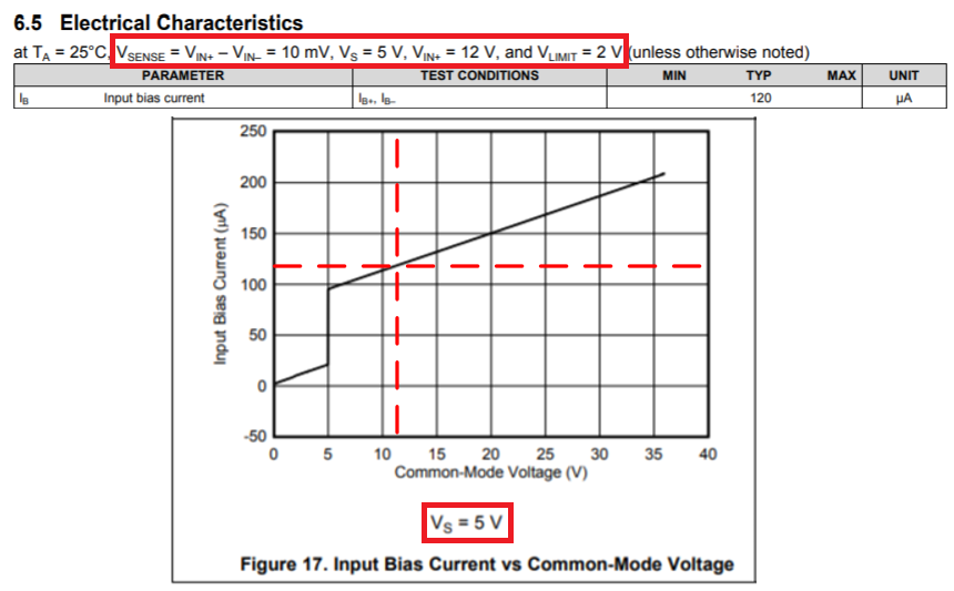
BTW,,, INA301 has TYP 120uA for Input Bias Current.

120uA is the average of two inputs current or just the absolute sum of two inputs current ?

I need that information to estimate leakage current at Power Off stage on board.

  • Hello Paul,

    Thanks for your interest in our current shunt monitor devices. The typical input bias current we provide in the electrical characteristics table actually corresponds to one operating condition. In the case of the INA301-Q1, this is at a common mode of 12V with a supply of 5V as indicated at the top of the table. You can verify this by looking at the input bias current vs common mode for 5V supply plot (figure 17). It so happens that this is the average of the two input bias currents when Vsense is 10mV.

    We often also include a graph that shows how the IB+ and IB- diverge with increasing Vsense. This graph is normally further into the datasheet in the applications and implementation section. Below in figure 2 is the graph you would fine corresponding to IB+,IB- versus Vsense.


    With the above posted graphs it often possible to approximate the input bias current for a particular power-off condition. This can be determined through deriving the input impedance. To determine the input impedance, we take the difference between two points on the input bias current vs. common mode voltage plot. In this case I take (20V,150uA)-(12V, 120uA) =(8V, 30uA). Thereupon we divide the calculated current by the calculated voltage to get the input impedance, 80V/(30uA)= 267kohm. If I do the same operation with points on datasheet figure 18 (below), I get (16.11V, 60uA)-(7.778V,30uA)= (8.332V, 30uA), which gives me a similar impedance value. For our devices these calculated values may not be exactly the same, but will be of similar magnitude and relatively close in value. Once you have the input impedance, you can use this value to approximate your input bias current at power off. For example, if your power-off common mode voltage is 20V, we would approximate the input bias to be 20V/267kohm = 75uA ( assuming the IB versus common mode for Vs=0  plot is not in the datasheet).

    As you are concerned with having very low input bias currents I would recommend looking at the INA190, one of our latest current shunt monitors designed specifically to have very low input bias currents.

    Although your primary concern is about current draw at power off, I would still like to add that the input bias current specification also matters for measuring low currents (<100uA).  If you are interested in learning more about that, I would recommend reading the following FAQ.

  • Hi Patrick

    if input bias current is wrriten by average of two inputs pin,

    I have to double TYP 120uA for two input pins ?

    I have to double the graphed input bias current value at figure 17 for two input pins ?

    I need absolute consumed input bias current for two pins.

  • Hi Paul,

    the INA301 has two inputs, +in and -in, and each input draws an input bias current. For a supply voltage of 5V and a common mode input voltage of 12V the input bias current is 120µA per pin, as specified in the datasheet. So, a total of 240µA is flowing into the scheme with the INA301.

    Have a look at section 7.2 of datasheet. In the schematic shown there you can see the INA301 on the right side and the shunt on the left. If the "power supply" is 12V and the INA301 is supplied by 5V, then the +in pin is also at 12V and Into the +in pin a current of 120µA is flowing, as said above. If the shunt is so small, that the voltage at the -in pin is also at about 12V, then also into the -in pin a current of 120µA is flowing. (This current will also flow through the shunt, by the way.) The "power supply" must source a total current of 240µA in this scenario.

    If the supply voltage of INA301 is 0V but the "power supply" is still 12V, the INA301 will still draw an input bias current. Figure 18 of datasheet shows that then 40µA will flow into each input pin of INA301. So, the "power supply" has to source a total current of 80µA.

    Kai