This thread has been locked.

If you have a related question, please click the "Ask a related question" button in the top right corner. The newly created question will be automatically linked to this question.

Extending the sensing voltage range of the INA219

Other Parts Discussed in Thread: INA219, INA226, INA220, ISO1541, OPA333

Dear e2e,

I am looking to use the INA219 as a system indicator in order to monitor a battery-powered audio amplifier. The battery is as 12V system, which fits the INA219 fine. However, the output of the power supply to the audio amplifier produces about 35V(TBD), and the INA219 only measures up to 26V. Is it possible to extend the range of the device by e.g. passing the shunt resistor readings(which are around 35V) through a voltage divider before passing them on to the INA219? Obviously one would have to take this issue into account when processing the readings from the registers, but is it practically possible? The INA219 has an input impedance of about 320kOhm, so I was wondering if a voltage divider consisting of e.g. 20kOhm resistors would be suitable. What are your thoughts on this? Do you have any other ideas as to how one can extend the range?

Thank you in advance,

  • Hi Peter,

    Thanks for the question regarding INA219...we have a higher common mode voltage product with the similar features as INA219...it is called INA226 and has a common mode input range specified to 36V.  Please have a look at that product and if you have more questions please reply to this thread...I am happy to assist you further. 

  • Hi Edward,


    Thank you for taking the time to reply to my question.


    I did consider the INA226, however the maximum range of 36V is a bit close to my voltage of 35V. And I do not know if the voltage of my application will be exactly 35V. It may end up being e.g. 38V, which would mean that the INA226 would still not be in range. The price tag is also somewhat higher for the INA226, and I liked the fact that the INA219 is available in an 8SOT-23 package. I would need several devices in my final design, and the PGA of the INA219 is required elsewhere. For simplicity, I would like to stick to only one type of IC, which is why I was inquiring about the possibility of just reducing the shunt/bus voltage by using a simple voltage divider.


    I do have an additional question: Both the INA219 and the INA226 are bi-directional, meaning that they can sense current in both directions. The block diagrams of the INA219 claims that the PGA is placed before the ADC. How do the INA219 produce the offset needed to avoid a dual-supply PGA and ADC? It appears that the INA226 solves this by sampling each shunt value directly, and subtracting them digitally.


    Thank you very much for helping me out.


    Best Regards

  • Hi Peter,

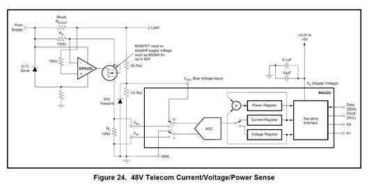
    I am glad you familiar enough with the INA226...it's too bad it was not a great fit in this application.  I am guessing that you have eliminated any possibility to monitor the current on the low side?  There is a way to translate the shunt measurement made at the 35V rail to ground, then use the INA219 within it's specified range...this concept is shown in Figure 24 of the INA220 data sheet...pasted here for your convenience...as you can see we create a ~5V supply referenced to the high CMV rail and translate the shunt measurement down to ground with a precision amplifier.

    An alternative might also be to similarly create the 5V rail from the 35V volt rail, hook the INA219 up directly to the shunt and use digital I2C isolator such as ISO1541 for the bus.  If this is an option you would consider let me know we can create a schematic for you as an example.

  • Hi Ed, 

    Thank you very much! I think I'll test out that solution with the raised 5V supply. Its pretty clever. 

    Raising the entire INA219 would be problematic, as I have several I2C devices on the same bus.

    I have two questions left:

    Why the 10k resistor on the non-inverting input of the OPA333? Wouldn't you rather go with one that makes sure that the impedance looking out of the OPA333 inputs would be similar? The impedance in the inverting input would be close to 100 Ohm, so why such a huge resister on the non-inverting input?

    How do you size the resistor to ground on the raised input? Is it any different from sizing the resistor in a normal zener-based voltage reference?

    Thank you very much.

    Best regards,

    Peter

  • Hi Peter,

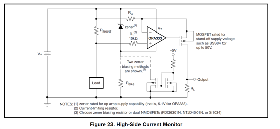
    Very good questions...the 10k resistor in there to provide protection to the OPA in the case of a load short...to determine the value for this resistor you can use this equation:

    (VCM - (VZener+VESD))/5mA

    Where VCM is the common mode voltage, in your application it is ~35V, VZener is the Zener drop, probably around 5V, and VESD is the forward voltage of the internal ESD protection diode that will become forward biased in the event of a load short which will pull the + input to the OPA below the negative power supply voltage at the OPA.  The 5mA is the maximum current allowed to flow in the OPA333 ESD diode and this value comes from the OPA333 specification.  In fact I have pasted here below pretty much the same biasing circuit for the OPA333 which is drawn in a way that makes this whole thing easier to see at least for me anyway :).  Putting numbers to your application I get:

    (35V-(5V + 0.5V))/5mA = 5.9kOhms.


    As far as the resistor in series with the Zener, pick an acceptable operating current for the Zener and size the resistor accordingly, I do not think there is anything special on this, just make sure to account for the INA219 current of 1mA which will also flow into the resistor.  In fact you might want to add a bit of margin to that current (i.e increase it a little) to allow fro any start-up conditions...often times IC's during power on will require more current than specified due to charging of capacitances, etc.  So maybe assume the INA219 peak current during any transient ia a few mA's.  So maybe scale the resistor to have at least 5mA.

  • Hi Ed,

    Thank you very much! You have been most kind in assisting me and answering my questions. I really do appreciate the time you and your colleagues spend on helping out in the e2e forum.

    Best rgards,

    Peter

  • Thanks Peter...keep Posting :)