Because of the holidays, TI E2E™ design support forum responses will be delayed from Dec. 25 through Jan. 2. Thank you for your patience.

This thread has been locked.

If you have a related question, please click the "Ask a related question" button in the top right corner. The newly created question will be automatically linked to this question.

Multiple feedback band pass filter

Hi everybody,

 I'm a newbie in electronic; right now, I’m trying to understand how to use an OpAmp to have a multiple feedback, second order band pass filter.

For what I know, 2 different solutions are possible:

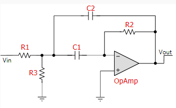
The first one (used by FilterPro) is the classic one:

The second one hasn’t the resistor “R3”:

Using this configuration, the gain of the circuit will always be equal to -2Q2.


To make this easier for you to answer, I'll number my questions.

1)      The configuration without “R3” is used in this document:

http://www.maximintegrated.com/en/app-notes/index.mvp/id/4622

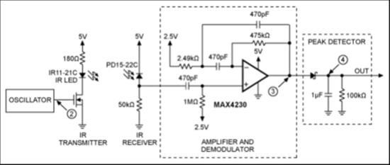
This is the schematic:

It is an IR proximity sensor, working at a frequency of 10kHz. As you can see, the signal in feeding the non inverting input (after passing through a passive high pass filter); the inverting input is connected to Virtual Ground (2.5V).

The Op Amp used here (MAX4230) has a 10MHz Gain-Bandwidth.

Knowing that:

Fr = 1 / (2π * [√ R1 R2 C1 C2])

Q = 0,5 * (√R2/R1)

G = -2Q2.

Passband BW = Fr / Q

I have:

Fr = 9846 Hz (close to 10kHz found in the text)

Q = 6.91

G = 95.38 (close to “100” found in the text).

Passband BW = 1.4249kHz

I used theese data with FilterPro, and I had exactly the same schematic (except for “R3” 157MΩ, of course):

But you can see that the Min GBW required in really, really high: 648MHz!!!

The formula used by FilterPro to calculate it is: 100 * Fc * Gain * Q.

In “Op Amps for everyone” (Ron Mancini, pag. 337) I’ve found another formula, for second order filters with a Q greater than 1:

Considered that I selected “Butterworth” as Filter Response, I can suppose to have an “ai” of 1.414.

Using this formula, I have a Min GBW reqd. of 66MHz, which is much lower than the one calculated by FilterPro, but still higher than 10MHz (MAX4230 Gain-Bandwidth): am I missing something?

2)      I read many positive comments about decompensated Op Amps. But, reading “Op Amp Applications Handbook” (Walt Jung), pag. 69, I read that: “unlike their fully compensated op amp relatives, a decompensated op amp can never be used with direct capacitive feedback from output to inverting input.”

Provided that the Gain will be adeguate (as required for the decompensated Op Amp), can I use a decompensated Op Amp for a multiple feedback, band pass filter?

3)      I’m planning to use SMD capacitors with 1% tolerance; I’d like to use SMD resistors with 0,5% tolerance, but they are not readily available. Is there a big difference in using SMD resistors with 1% tolerance?

Considering that I have to use 3 resistors, is it a problem if I use 1 (or 2) resistors with 0,5% tolerance, and the missing ones with 1% tolerance? Am I going to obtain a performance beetwen the one with only 1% resistors and the one with only 0,5% resistors?

4)      Using FilterPro, I see that when I get a Q higher than 15 (as always: multiple feedback, second order band pass filter) I have an asterisk close to the Q value (like: 16*). I guess it means that I’m asking too much, so is it correct to say that, until I don’t have that sign (so, until the value of Q is < 15) the circuit is expected to work properly?

Regards,

Marco

  • Hi Marco,

    I most often handle the active filter inquiries, but was away on vacation until today. You have a surprisingly good grasp of active filter concepts for being a "newbie." I will attempt to provide answers to your questions.

    But you can see that the Min GBW required in really, really high: 648MHz!!!

    The formula used by FilterPro to calculate it is: 100 * Fc * Gain * Q.

    In “Op Amps for everyone” (Ron Mancini, pag. 337) I’ve found another formula, for second order filters with a Q greater than 1:

    Considered that I selected “Butterworth” as Filter Response, I can suppose to have an “ai” of 1.414.

    Using this formula, I have a Min GBW reqd. of 66MHz, which is much lower than the one calculated by FilterPro, but still higher than 10MHz (MAX4230 Gain-Bandwidth): am I missing something?

    FilterPro uses a general, conservative GBW calculation that covers the Sallen-Key and MFB filters that it synthesizes. Its high GBW is often overkill, but when you use it you can be assured that gain, phase, delay, etc., response distortions will be minimized.

    I have attempted to find the basis of the active filter GBW equation you cited provided in "Op Amps for Everyone." It originated from a filter text written in German. I find it produces sufficient GBW for the filters I have tested using it as the basis. When the filter Q and gain are low the GBW of the FilterPro and text equation come out quite close. I had never used the equation for an active filter having a gain of 100 V/V which is very high for a single stage filter.

    I set up your MFB band-pass filter with our TINA Pspice simulator using op models where I programmed the GBW for 650 MHz, 65 MHz and 10 MHz. Surprisingly, the filter responses were nearly identical in the pass-band, below the pass-band, and a few decades above the pass-band. Where they began to deviate most from each other is at frequencies well above the pass-band. The lowest GBW op amp rolled off at the lowest frequency and so forth, as expected. 

    All references that I find to the two resistor MFB band-pas filter show it as an inverting filter. However, the application circuit you reference shows the non-inverting input being driven. When I run a simulation on it, the response is nearly identical, but the response flattens off at 1 V/V (0 dB) instead of continuing to roll off at 20 dB/decade as it does for the inverting case.

    2)      I read many positive comments about decompensated Op Amps. But, reading “Op Amp Applications Handbook” (Walt Jung), pag. 69, I read that: “unlike their fully compensated op amp relatives, a decompensated op amp can never be used with direct capacitive feedback from output to inverting input.”

    Provided that the Gain will be adeguate (as required for the decompensated Op Amp), can I use a decompensated Op Amp for a multiple feedback, band pass filter?

    I don't think there is a simple answer to this question because it depends on the gain-phase characteristics of the uncompensated amplifier, its complex open-loop output impedance (Zo) and the network topology being placed around the amplifier. It would come down to the remaining phase margin when the whole system is put together.

    Applying uncompensated, or under compensated, op amps is a way to get wider bandwidth but places constraints on the closed gain that can be applied to the amplifier. Modern op amps are available with very high GBW so uncompensated op amps are much less commonly applied as they were decades ago. I suggest using a compensated op amp for the active filters. The filter topologies are designed to be used with compensated amplifiers that should remain stable when correctly applied.  

    3)      I’m planning to use SMD capacitors with 1% tolerance; I’d like to use SMD resistors with 0,5% tolerance, but they are not readily available. Is there a big difference in using SMD resistors with 1% tolerance?

    Always use the most precise, lowest tolerance passive components that your design allows. Filter sensitivities to component values can be high and the response can be surprisingly distorted relative to the ideal. Here in the US distributors such as DigiKey, Mouser, and others commonly stock 0.1 % tolerance SMD resistors. Currently, I am using some 0.1 % 0603 Panasonic SMD resistors in another project. Vishay and KOA are some other companies that produce the 0.1 % tolerance SMD resistors.

    Be sure to use a high quality dielectric capacitor such as C0G for the capacitors. Some ceramic capacitor dielectrics such as X7R can produce distortion which may be evident in the filter's output.

    Considering that I have to use 3 resistors, is it a problem if I use 1 (or 2) resistors with 0,5% tolerance, and the missing ones with 1% tolerance? Am I going to obtain a performance beetwen the one with only 1% resistors and the one with only 0,5% resistors?

    You can combine resistors to make up the values you need, but I would use the lowest tolerance resistors that satisfy the application requirements.

    4)      Using FilterPro, I see that when I get a Q higher than 15 (as always: multiple feedback, second order band pass filter) I have an asterisk close to the Q value (like: 16*). I guess it means that I’m asking too much, so is it correct to say that, until I don’t have that sign (so, until the value of Q is < 15) the circuit is expected to work properly?

    Many filter books recommend keeping the Stage Q to 10, or less, for accurate active filter response from filters made up of single op amp stages. Often, alternate topologies to the Sallen-Key and MFB are used when high Q and/or high gain is required from an active filter. There alternate topologies usually require 2 to 4 op amps per stage. The higher loop gains and buffering of nodes results in more precise responses.

    FilterPro places a red asterisk alongside any filter response where it detects the Q will be greater than 15. The original intent was to have a message indicating that a lower Q alternative should be considered, but somewhere along the way that message was lost.

    I hope this helps provide some guidance.

    Regards, Thomas

    PA - Linear Applications Engineering

  • Hi Thomas,


    the “Quality Factor” of your answer is incredibly high!!!!

    It requires 1 Giga-thanks of Thanking-Bandwidth; If I were FilterPro, I would give you 5 asterisks, at least.

    Thank you so much for all the time you spent in order to give me such a “state-of-the-art” answer, I’ll follow your indications.


    Marco.