This thread has been locked.

If you have a related question, please click the "Ask a related question" button in the top right corner. The newly created question will be automatically linked to this question.

XTR111 Design

Other Parts Discussed in Thread: XTR111, XTR117, XTR105, XTR106, XTR115, TINA-TI, REF5050, XTR110, XTR300

From Engineer:

Hi Collin:
 
My name is Ignacio Melchor, I'm from Mexico and currently I'm studying electronic engineering.
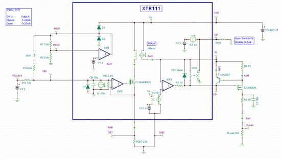
 When I knew the XTR111, I was really surprised because it is a wonder, I did a diagram basing on information from this website:
 http://e2e.ti.com/support/amplifiers/precision_amplifiers/f/14/t/120905.aspx
 
 Only that I had a question regarding the choice of the resistance R set, according to my calculations to get 20 mA maximum current value would be as in the attached image: R SET CAL.
 Is it right to the value of R set?

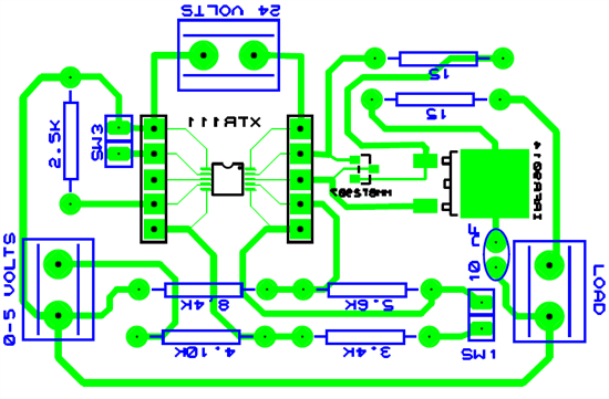
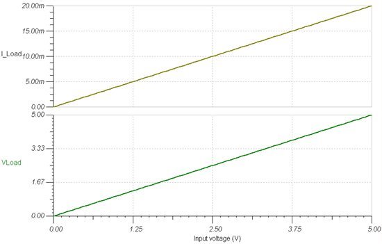
 I have another design of a power source, built with operational amplifiers, which can be simulated in ISIS as in this video:
 http://www.youtube.com/watch?v=iezEShR0cjI&feature=youtu.be
 How could simulate the XTR111?
 
Greetings.

  • Hello Ignacio,

    Yes, the XTR111 is a very nice integrated device. 

    Your RSET calculations are correct.  a 2.5k resistor will provide for a 20mA output span with a 5V input source.

    The youtube video is actually a current sink, not a current source like the XTR111.  The XTR111 was created for 3-wire current-loop transmitter applications.  Other devices like the XTR115 - XTR117, XTR105, XTR106 and others were created for 2-wire current loop transmitter applications.  Typically 3-wire applications are current sources, while 2-wire applications are current sinks.  Please be sure you are looking for a current source when you're using the XTR111.

    I'm not familiar with the ISIS simulation program, but I do have a very basic simulation model you could use with TI's TINA-TI SPICE program which can be downloaded at the link below:

    http://www.ti.com/tool/tina-ti

    The simulation model is attached here:
    7558.XTR111_User.TSC

    This is an unofficial SPICE model that was created to help customers and other interested parties understand the fundamental operations of the XTR111.  It will not accurately simulate most datasheet parameters but will be useful in understanding how the product operates. 

    Best Regards,
    Collin Wells
    Precision Linear Applications

  • Thank you very much for your quick response Collin, now I understand better the operation of XTR111, and the Tina is very complete software for simulations.

    If I have any further questions, I will through the forum. Greetings. :)

  • Hi Collin I hope you are very well... 

    With your help, I built a PCB with the XTR111, based on the following diagram:

    I used the MMBT2907 pnp transistor and the mosfet IRFR9014, I checked all the conections very good, but the problem is when I supply the voltage of input fron 0 to 5 volts, the output generates incorrectly the value of current, because de output provides from 10 mA to 20 mA, What you could suggest to correct this problem?


    Here is a video from the PCB working: http://www.youtube.com/watch?v=yrm7-IdwwE0&feature=youtu.be

    Regards.


  • Hello Ignacio,

    Thank you for the Youtube video, it makes it very easy to view the same thing you viewed in the lab. 

    I placed your circuit into the SPICE model for the XTR111 that I previously provided you.  You can download the circuit I used for testing from this link: 

    3771.XTR111_IMS_Circuit.TSC

    The results can be seen below:

    VREG Switch Open:
    Results:  I_Load = 0 - 20mA

    VREG Switch Closed:
    Results:  I_Load = 10.9 - 20mA


    The simulation matches the results shown in your Youtube video. 

    The output level of 10.9mA when you apply 0V can be explained by looking at the voltage that makes it to the input pin of the XTR111.  With a 0V input at the 4.1k resistor, the combination of the 3.4k and 4.1k resistors result in about 2.73V to the input pin of the XTR.   Before we talk about how to fix the circuit, I would need to know what your desired output range is for the 0-5V input. 

    What output current range do you expect for this circuit when you input 0-5V (4-20mA, 0 -20mA, other)?

    Thanks,
    Collin Wells
    Precision Linear Applications 

  • Hi Collin, thanks newly by your response

    I need get a 4-20 mA when I supply 0-5 volts in the input.


    Regards.

  • Hello Ignacio,

    Thank you for the additional information.  I would suggest reading through the "4-20mA Output" section of the XTR111 datasheet located on page 17.  It provides instructions for achieving a 4-20mA output from a 0-5V source. 

    Once you read through the theory, you could try to download TI's SPICE program, TINA-TI ( http://www.ti.com/tool/tina-ti ), and modify the circuit I previously attached for you with the new component values. 

    Best Regards,
    Collin Wells
    Precision Linear Applications

  • Hi Collin, thanks for the suggestion, I was building a new printed circuit boards with separate components, I'll go back to school the following Monday, to make new tests in the laboratory.

     I modified the simulation by adding the voltage reference you suggested, I sent the simulation to your email, because the publisher would not let me insert here.

    How can I get some graphics for the new simulation? Such as you did like this:

     Thank you Collin, you have a great weekend.

  • Hi Ignacio,

    Thank you for the updated TINA file.  I've posted it below so others can view it as well. 

    The results look correct now.  When the input voltage is swept from 0-5V, the output current is 4-20mA and the output voltage is 1-5V into a 250Ohm load. 

    Please be aware that although it is not required it is usually convenient to use the XTR111 regulator to create the 5V reference used for the 4-20mA level shifting.  Another option would be to use the XTR111 regulator to power a precision +5V reference such as the REF5050. 

    The plots above were created by running a "DC Transfer Characteristic" which can be found under the "Analysis / DC Analysis"  Once the pop-up window appears (2nd image below) select the source or component you would like to vary and then plot away!


    Regards,
    Collin Wells
    Precision Linear Applications

    0508.TEST_XTR111_FromIMS.TSC

  • Hi Collin finally the XTR111 is working well, now the output can give 4mA when the voltage of input is 0 Volts. Thanks by your help and your tips.

    Here is the link from youtube: http://www.youtube.com/watch?v=2QhWMFzJFZs&feature=youtu.be

  • Great news and good work!

    It was fun to watch the video on youtube, thanks for that.

    Regards,
    Collin Wells
    Precision Linear Applications

  • Dear All,

    Can anyone please provide me any information regarding any IC from the TI that can be used as 3-wire 4-20 mA sinking transmitter? 

    Your help would be very appreciated.

    Regards,

    Muhammad Rehan

  • Muhammad,

    The XTR110 and XTR111 are two ICs which can be used for 3-wire 4-20mA loops.

  • Mr John,

    Thank you for your kind reply. Can you please elaborate little bit more that how can i use these ICs as 3-wire sinking 4-20mA transmitters?

    Regards,

    Muhammad Rehan

  • Muhammad,

    The typical implementation for a 3-wire 4 to 20mA system is shown below with the XTR111.

    Looking at your question, you specify a "sinking" transmitter, which is uncommon in 3-wire circuits, notice that the transmitter is sourcing current into the load. Sinking would require that the load on your receiver side be referenced to the power supply voltage instead of ground. Is this actually required in your application or will the above circuit work?

  • Mr. John,

    The above mentioned typical implementation is indeed sourcing. and yes I require the sinking mode that the load on your receiver side be referenced to the power supply voltage instead of ground. The above circuit won't work.


    Regards,

    Muhammad Rehan.

  • Muhammad,

    TI currently does not have a 3-wire transmitter IC intended for sinking 4-20mA rather than sourcing. However, one solution for your application would be to build a discrete 4 to 20mA transmitter. The circuit below uses 1% resistors and achieves an accuracy better than 1% over the 4-20mA range. It is designed for a 0 to 5V input on a 24V loop supply.

  • Mr. John,

    Thank you very much for your kind suport.

    Regards,

    Muhammad Rehan

  • Hello.
    Is it possible by any chance to have a file spice model i can feed into any spice simulator ?
    Or, is there a way, opening the project within TINA to export the spice model of XTR111 into a text file ?
    I've noticed that the XTR300 has a spice model, but not the XTR111 unfortunately.
    Thanks.