This thread has been locked.

If you have a related question, please click the "Ask a related question" button in the top right corner. The newly created question will be automatically linked to this question.

LMP91000 layout

Other Parts Discussed in Thread: LMP91000, MSP430F2274

hi, I´m trying to do lmp91000 - sensor pcb.

measuring the current consumption, there is 0,6 uA. 

I guess that is sleeping, but I can notprogram through the i2c lines.

Currently I have ​​a program that works for LMP91000 Evaluation Board http://www.ti.com/lit/ug/snau029/snau029.pdf  connected to msp430f2274 but does not work in the board design.

Questions:

1) ¿the signal i2c is to low for comunication ?

2) ¿ high noise level in the design?

Best regards,

Juan

  • Juan,

    you need to pull the pin MENB (Module Enable) low, to activate the I2C interface. I would guess this is your problem?
    Andreas

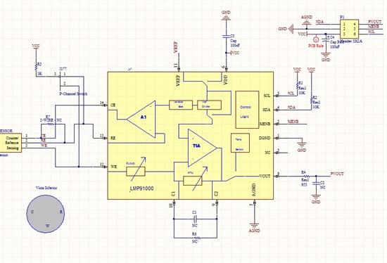
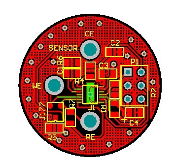
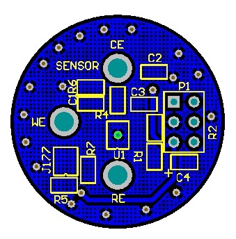
  • Hi Andreas thanks for reply, I already have the program working on the evaluation module. Now I'm trying to use my own board using the lmp91000 without success (I attached the layout and schematics).
     The only difference I noted are the fet transistors for the I2C lines.
    Note that in the evaluation module the MENB line is not connected to Vdd ( in the schematics, the MENB line is jumped to Vdd). So my question is:
    
    1)Do I need those fet transistors?
  • Hi Juan,

    have a look to the data sheet, pg 13. It says

    In order to start any read or write operation with the

    LMP91000, MENB needs to be set low during the whole communication.

    If you do not pull MENB low, the I2C interface is locked.

    If you have MENB open, it will not work.

    I did not design the eval board, but I do not see a reason, why you would need them.


    Andreas

  • Andreas, the LMP91000, MENB is controlled by msp430f2274 .

    The program working on the evaluation module but not in my pcb.
    The only difference is the fet transistors for the I2C lines, I need those fet transistors?

    Juan

  • Hi Juan,

    the FET transistor in the evaluation board were put in order to perform a level shift. In the Eval board the LMP91000 is supplied at 5V (from SPIO4 board) and so the pull up resistors are connected between 5V and SDA/SCL pin. The micro controller on the SPIO4 has a 3.3V I2C, so   to correctly work with LMP91000 there is the needs of the FET to implement the level shift.

    Said so, if in your application the LMP91000 and the microcontroller are supplied by the same source (Same voltage level) you do not need the FET. Viceversa with the LMP91000 is supplied at 5V and the micro at 3.3V, you need the FET.

    I suggest you to use the same supply voltage for both devices (3.3V).

    regards,

    Domenico.