This thread has been locked.

If you have a related question, please click the "Ask a related question" button in the top right corner. The newly created question will be automatically linked to this question.

ECG Design using INA128

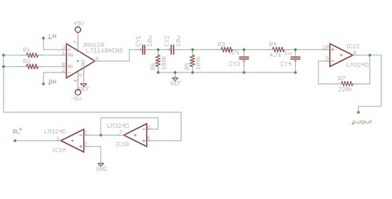
I came across this basic 3 lead ECG circuit using INA 128.


Please help me in understanding how to use the REF pin here. Also GND pin has been mentioned here in the right leg drive part. Are REF and GND used interchangeably here?

Should we consider driving the REF pin through an unity buffer with some voltage?

Please help us point out any anomaly in this circuit.

We managed to get a not so good looking ECG signal once, but we are not getting output consecutively in the next trials.

What could we be doing wrong? Our output was obtained on a DSO. We had tried using audio jack on laptop to get the signal but we couldn't get any positive outcome from that method as well.

I would be grateful if you can help us smoothen some issues, mainly regarding connection of REF pin.
 

  • Hello Vishnu,

    We have an E2E Design Note concerning ECG acquisition. Here is the link:

    http://e2e.ti.com/support/amplifiers/precision_amplifiers/w/design_notes/2437.ecg-heart-signal-acquisition.aspx

    I recommend looking at the presentation "Design Considerations for ECG Systems". Page 32 discusses the use of the Ref pin to remove the offsets due to the electrodes, device offset, etc.

    You may also find the following link useful:

    http://www.egr.msu.edu/classes/ece480/capstone/spring13/group03/

    This group created an ECG demo board that basically implements the circuit given in the aforementioned presentation.

  • Thank you so much Pete Sir. 

    Very happy to receive those links. I will study all of them to see if it can help us.

    Appreciate the amazingly fast response especially from an ECG design expert.

    Thank You.