This thread has been locked.

If you have a related question, please click the "Ask a related question" button in the top right corner. The newly created question will be automatically linked to this question.

AMC1100 - Mains Voltage Measurement - Powering the Device?

Other Parts Discussed in Thread: AMC1100

Hi,

I am using AMC1100 in a system to measure mains AC voltage in an isolated way. (Schematics at the bottom of this post)

I have the following questions:

1. I would like to know how to connect the GND1 pin.  Should it be connected to the Neutral Phase (as per the datasheet) or PGND (Which is derived from a rectifier)?

2. I would also like to know how to generate VCC1.  Do we need to make a new power supply system from from the active phase, or can we power the AMC1100's VCC1 via a regulator from the UCC28710D's VCC Supply?

Thanks 

Stomp!


Information Below:

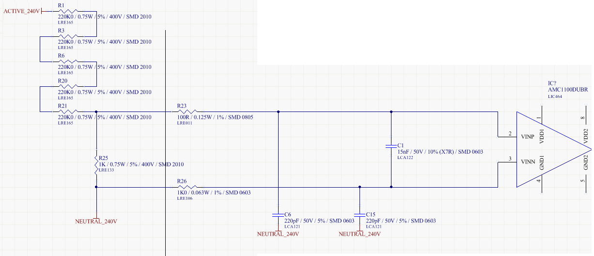
I have a voltage divider and anti-alias filter feeding the AMC1100 directly from the phase active and neutral lines as in the image below:

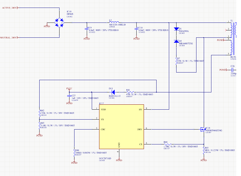
I am powering the system using the TI UCC28710D to generate an isolated power supply as per the image below:

  • Hello Stomp,

    The connection of GND1 depends on the connections of the analog inputs to the AMC1100. From the schematic you included in your post it seems that you are trying to monitor the “ACTIVE_240V” voltage with respect to “NEUTRAL_240V”. If that is the case, then my recommendation is to connect GND1 to the “NEUTRAL_240V” point.

    To generate VCC1 you have three options:

    1)      You could generate a power supply from the active phase, or

    2)      You could generate an isolated power supply from the UCC28710D's VCC Supply following the idea shown in the article “Isolated sensing systems with low power consumption” available at http://www.ti.com/lit/an/slyt600/slyt600.pdf

    3)      You could  generate an isolated power supply from the controller side (VDD2) supply following the idea shown in the TI design “Isolated Current Sensing Reference Design Solution, 5A, 2kV”  available at  http://www.ti.com/lit/ug/slau521/slau521.pdf

    Hope this helps.

    Best regards,

    Jose

  • Hi Jose,
    Thanks for your detailed response.

    For others using the device we created a capacitive (transformer-less) power supply using a mains rated capacitor, resistor and zener diode to generate the VCC for the mains side of the AMC1100.

    Boards are back from manufacture and testing has gone well.

    Thanks again for pointing us int he correct direction.
    Cheers
    Stomp!.
  • Hello Stomp,

    You are very welcome! I'm glad to see that your design is working well.

    Best regards,
    Jose