Because of the holidays, TI E2E™ design support forum responses will be delayed from Dec. 25 through Jan. 2. Thank you for your patience.

This thread has been locked.

If you have a related question, please click the "Ask a related question" button in the top right corner. The newly created question will be automatically linked to this question.

Differential input charge OP amp

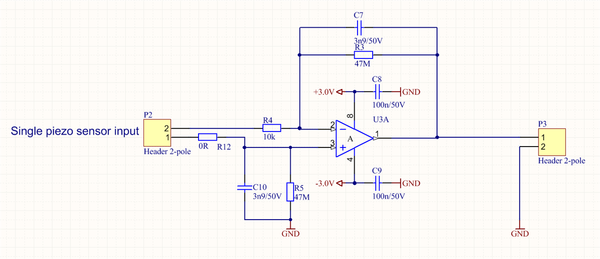
Hello, I'm working with piezo film sensors and I'm using an OP amp to create a differential input charge amplifier. The OP map is supplied with both positive and negative voltage (V+ = 3.0V and V- = -3.0V) so the output swings both positive and negative around GND. I'm however not sure how to create a differential input charge OP amp under these conditions with the purpose to cancel out 50Hz common mode noise.

I have attached the schematic for the charge amplifier circuit I'm using today.

Have I connected it correctly to get differential inputs ? will this circuit cancel out any 50/60Hz common mode noise ?

Best regards

Ronny

  • Hi Ronny,

    Charge amplifiers are sometimes employed with a sensor that in response to a stimulus changes its capacitance. The gain is established by the ratio of the amplifier feedback capacitance, to the capacitance of the capacitive sensor, Av = (-jXf) / (-jXs). A feedback resistor is included to provide a path for the op amp's input bias current. Therefore, your peizo sensor would have to appear as a changing capacitance to be usable in a charge amplifier. 

    The circuit you have shown is for the most part a classical difference amplifier topology. It exhibits a voltage gain based on the resistor ratios. The exception is that R12 would have the same resistance as R4. In that case, the gain would be equal through the two inputs and the common-mode rejection of the op amp would provide rejection of common-mode signals (CMRR). With R12 equal to 0 ohms the circuit is unbalanced and the CMRR would suffer. The capacitors in the circuit roll-off the bandwidth producing a low-pass filter response. Is this what you intended?

    Several years ago we did come up with a differential charge amplifier design, but it was quite an extensive design. We simulated it, but never built it.

    Regards, Thomas

    PA - Linear Applications Engineering

  • OK, that is good info, thanks a lot! :-) and the circuit will as you mentioned have a Low pass behavior which is ok for my application.

    Best regards

    Ronny

  • Hi Ron,

    Check out this white paper: http://www.ti.com/lit/an/sloa033a/sloa033a.pdf

    You don't mention whether the piezo element is located on the PCB, or connected via a cable. If through a cable, you'll have a few other things to deal with; proper shielding of the cable for one. Movement of a cable will also create issues. 

    I've used piezo film in a number of different projects over the years; as a motion detector in a car alarm (the film element was mounted directly to the PCB), as a "wind" sensor in a toy product, as a "sound pickup" in an acoustic guitar and in a version of a "singing balloon" in which the film was bonded to the balloon film and driven with a high voltage amplifier. Sometimes good shielding of the element is all that's needed. 

    Many years ago (over 20) a division of AMP (Atochem) made various sensors. You might be able to find the papers they produced; tons of good information there.

    For reference, check out the following links. 

    http://electronicdesign.com/analog/special-amplifier-conditions-piezo-film-signal

    http://www.eng.hmc.edu/NewE80/PDFs/PiezoElectronics.pdf

    http://www.imagesco.com/piezoelectric/piezo_film_faq.pdf

    Good luck!

    Mike T.

  • Hi MIke!

    Thanks for the great info! :-)

    My piezo sensor i connected to the PCB via a cable. I used a differential input charge amplifier circuit arrangment proposed by Texas in the document:

    www.ti.com/.../slyt369

    , with the purpose to filter any common mode 50/60Hz noise but I have also thought about if it is necessary to use a shield for both the piezo sensor itself and also the cable.

    My initital thought/intuition is that a shield is of course necessary but this will add complexity and cost to the complete sensor including the cable and if it is possible to manage without a shield that is the way to go.

    I really appreciate your input and I will check out the AMP/Atochem sensors.

    Best regards

    Ronny