This thread has been locked.

If you have a related question, please click the "Ask a related question" button in the top right corner. The newly created question will be automatically linked to this question.

LM311P VS LM311N

Other Parts Discussed in Thread: LM311

Hi All,

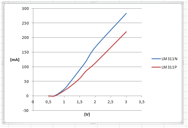
what is the difference between this two component?

The same circuit work fine with the LM311N but when I use the LM311P it doesn't work.

  • Antonio,

    Two different die designs. Created by two separate companies. Both device work, if design does not violate some specification.

    C1 can push pin 2 out of the valid common mode range. It can make pin 2 peak above VCC and below ground. Most concerning is below ground.

    Try removing C1; does that help?

  • Hi Ron,
    tank you for your answer, infact I removed the C1 and the circuit work fine.

    I was not able to motivate the wrong behavior.

    Regards
    Antonio
  • Hi Ronald,

    below you can see two trace on pin 2 of U1, the first is with LM311P, you can see a spike of -2.987V

    While the second with LM311N:

    The negative spike is 0.7V.

    According the datasheet of the lm311N:

    Why all work with LM311N?

    thank you in advance.

    Antonio

  • Antonio,

    I suspect LM311P does not have a parasitic diode from input to GND pin and LM311N does have a diode.

  • Hi Ron,

    both LM311P and LM311N have the parassitic diode, infact I used the Multimeter to meseaure if diode on pin 2 to ground was present in both models.

    I tried to characterize it for both the OPAMP:

    any suggestion?

    Thanks in advance.


    Regards

    Antonio

  • Antonio,

    It makes sense that both have diodes. However the -2.987V peak pulse that was observed means the diode is being over-stressed.
    You have at least two choice , keep the capacitor out or use the LM311 that seem to ignore the transient.

    If you would like to try something else. Sweep pin 2 from 0V to -0.8V and see if if the output goes high. If it does, that is called phase reversal.