


Other Parts Discussed in Thread: TL084
Hello.
I have the following design in one board:

But the system is failing with all the LM074 that we currently has in stock, and it works with the LM084.
The input of the system is an square signal of 80kHz wich moves between +15V and GND.
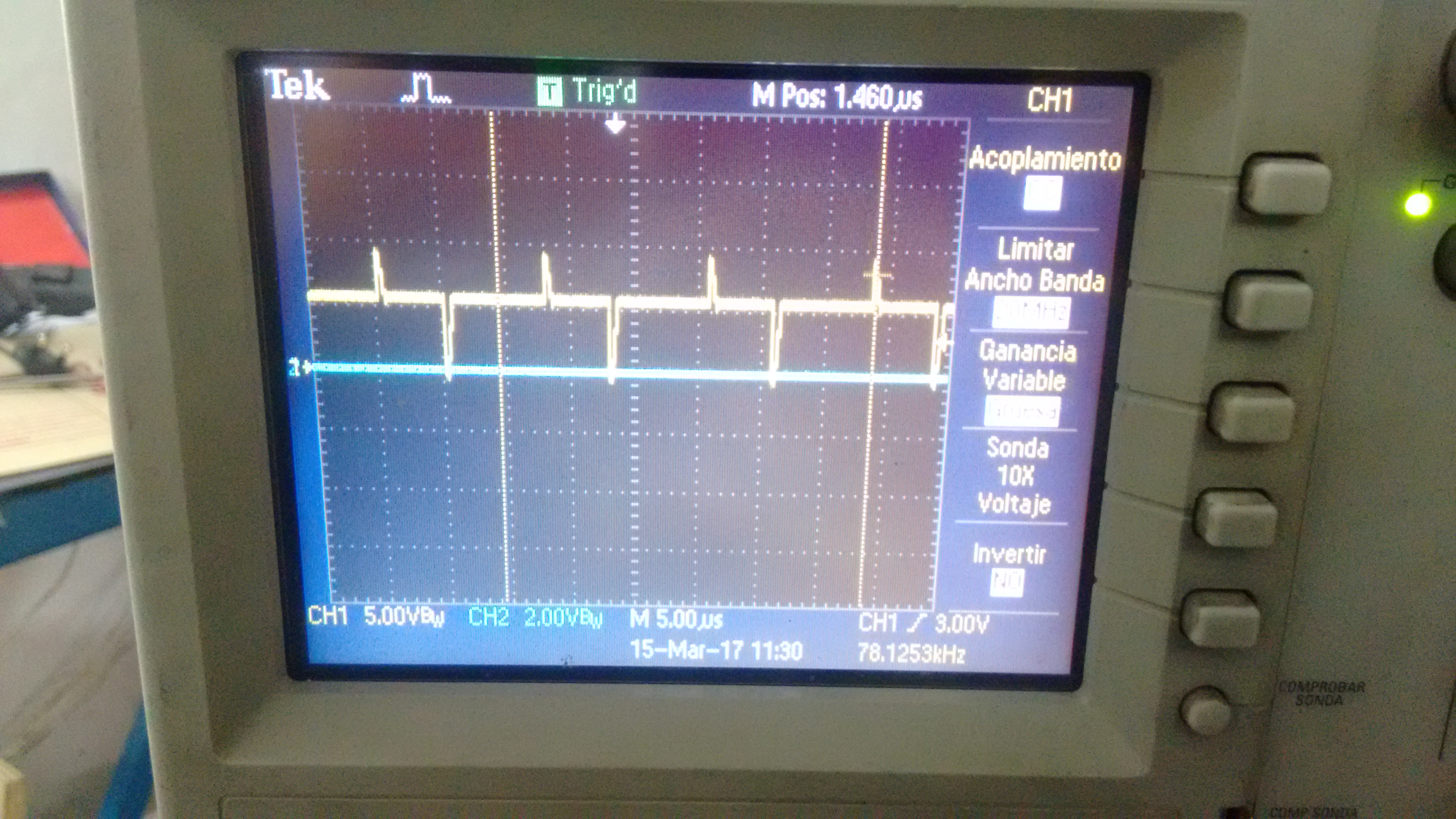
The output whith the LM084 is the same as the simulated:
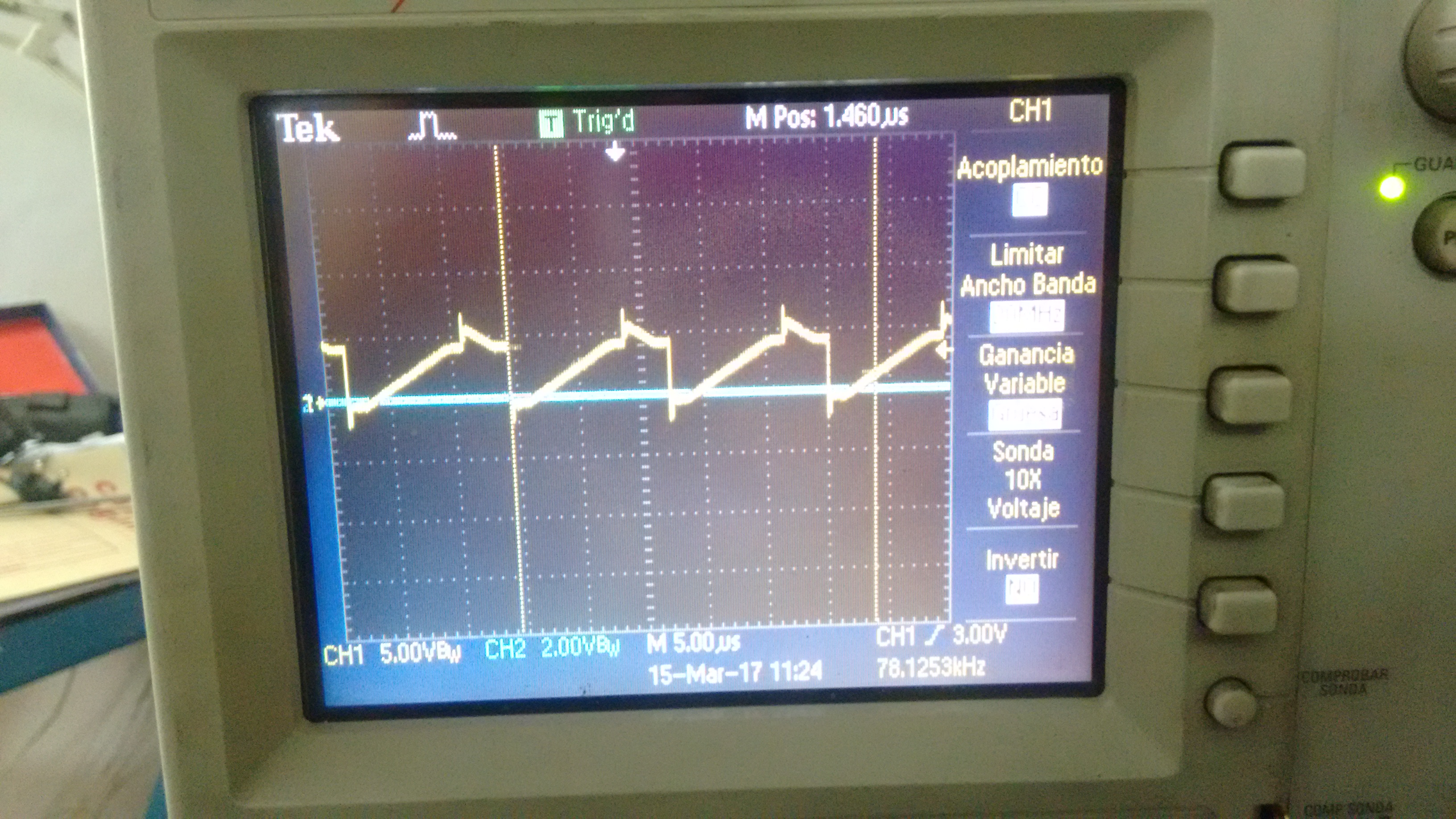
And the output with the LM074 is something that I can't find how to simulate:
Trying to understand more the circuit I simulated, and measured the current AM1, the simulation shows an square current of +/- 10mA
- Is the TL074 capable of produce this current needed for this circuit?
- Is the TL084 capable of producing it?, in the datasheet I can't find how to obtain the maximum Iout.
- Is there something wrong with my circuit that could produce these different output with the TL084 and TL074?
Pd: With webench I could produce some circuit that use the same topology, so I guess that the circuit is fine
https://webench.ti.com/appinfo/webench/scripts/SDP.cgi?ID=ADA47375AE08A8B5
