This thread has been locked.

If you have a related question, please click the "Ask a related question" button in the top right corner. The newly created question will be automatically linked to this question.

INA196: Using INA196 for monitoring current on a 110V DC rail

Part Number: INA196
Other Parts Discussed in Thread: INA138, TIDA-00332, ISO1541, TIDA-00313, INA226, ISOW7842, INA260

Hi,

The common mode voltage of INA196 is limited to 80V.

How can I extend the common mode range of INA196 to measure a 110V DC rail with a peak current capacity of 1A?

Can I use a resistor divider at the sensing input of INA196 as shown in the image?

Also, please verify whether my calculations are correct.

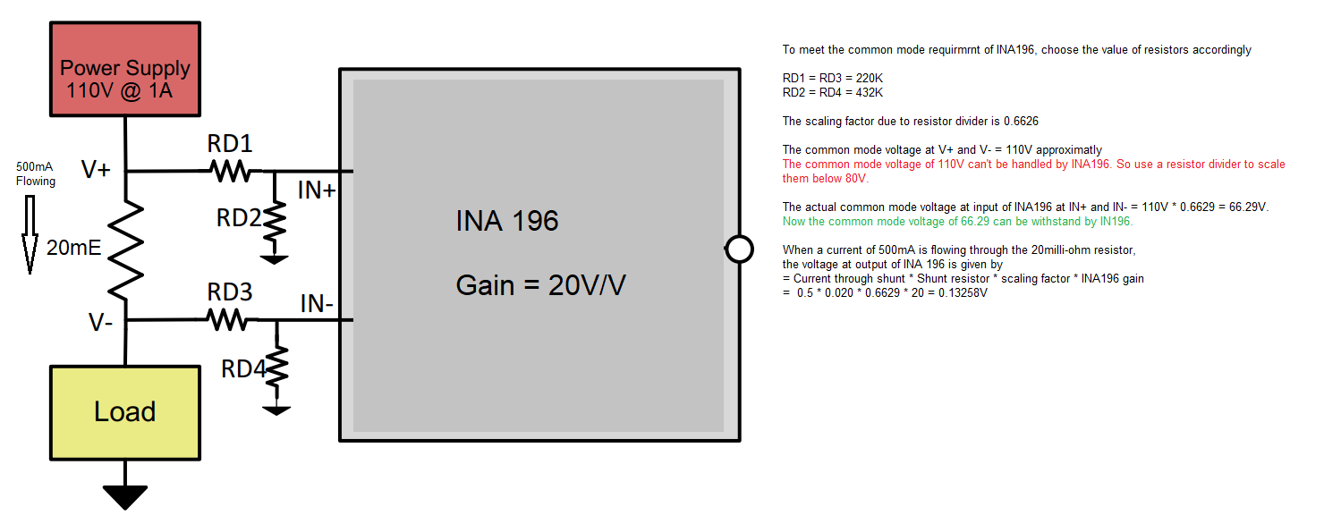
To meet the common mode requirement of INA196, choose the value of resistors accordingly

RD1 = RD3 = 220K
RD2 = RD4 = 432K

The scaling factor due to resistor divider is 0.6626

The common mode voltage at V+ and V- = 110V approximately
The common mode voltage of 110V can't be handled by INA196. So use a resistor divider to scale
them below 80V.

The actual common mode voltage at input of INA196 at IN+ and IN- = 110V * 0.6629 = 66.29V.
Now the common mode voltage of 66.29 can be withstood by IN196.

When a current of 500mA is flowing through the 20milli-ohm resistor,
the voltage at output of INA 196 is given by  
= Current through shunt * Shunt resistor * scaling factor * INA196 gain
=  0.5 * 0.020 * 0.6629 * 20 = 0.13258V

Based on above calculation, I am getting 0.1325V for 500mA current. Do this calculation is correct?

Thanks in advance
DEEPAK V

  • DEEPAK,

    A couple of things about this circuit - first is that when you add large resistors to the inputs, you have to take into account a few things.  First is that the large resistors will have input bias currents flowing through them, and as this is not a rail-to-rail op amp or instrumentation amp, the input currents are larger than usual (10s of uA).  If we were to assume that there are 10uA flowing into both the VIN+ and VIN- pins, then you could see 10uA * 220KΩ = 2.2V of drop across RD1 and RD3.  Assuming that the currents remain equal, this isn't as big a deal, but if the resistor tolerance is off, that can be a big voltage offset added.  Also, as the sense voltage increases, the input bias currents change, with VIN+ getting larger and VIN- getting smaller.  If you have, for instance, VIN+ taking in 11uA and VIN- taking in 9uA, then you would see a voltage drop of 2.42V on VIN+ and 1.98V on VIN-.  This is a difference of 440mV which goes into the offset, which would basically make the part unusuable.

    Another thing to note is that if you try to measure 500mA through 20mΩ, you would generate a Vsense of 10mV, which is below the recommended and specified 20mV minimum that this part supports for linear operation (see this article for more information).

    Essentially what I'm saying is that while you can kind of use the part with the resistor dividers on the input, it's not really recommended as the errors will be great and the functionality will be limited.  Also, the INA196 is not good for measuring small Vsense currents.  For high voltage measurements, we do have some other design ideas - I'm sure you've seen some in that tech note you pulled the drawing from.  Look at TIDA-00332 for instance, which uses an INA138 and can go to hundreds of volts depending on the MOSFETs chosen.  It's minimal additional circuitry and fairly accurate even down at low Vsense voltages.

    I would also suggest, if you haven't already, to watch the video series on current shunt monitor use and error calculation.  It may help you understand the application use cases for our sense amplifiers and what kind of performance to expect.

  • Hi Jason Bridgmon,

    Thank you with all my heart for pointing out the possible difficulties that will encounter from the design attached to the earlier post.

    I have gone into detail through the suggested reference design TIDA-00332. And it is the right solution I am also looking for. But our requirement needs slight modification.

    In our requirement, the current has to be monitored from a DC High Voltage rail but it will take different DC voltage based on application.

    The possible voltage and current rating on this rail is as given

    1. 110V @ 0.8A

    2. 90V @ 1.2A

    3. 60V @ 1.4A

    4. 20V @ 3A

    5. 5V @ 4A

    So I have made some modifications on TIDA-00332 to make it suitable for operating from 110V to 5V at 0.8A to 4A respectively.

    These includes

    1. Replacing the 12V Zener diode D1 with 3.3V Zener diode 'MM3Z3V3B'.

    2. Reduce the value of 200K resistor R1 and replace it with 22K. To withstand 110V, resistor with a 1W rating is chosen.

    Please find the attached image of schematic and let me know  will it suit our requirements?


    I have also attached the TINA simulation file for this design.

    HV_current_sense2.TSC

    We also have the same current sensing requirment on the High voltage negative rail

    1. -110V @ 0.8A

    2. -90V @ 1.2A

    3. -60V @ 1.4A

    4. -20V @ 3A

    5. -5V @ 4A

    Is there any way to use INA138 for this application to sense current on -ve High voltage rail? Please suggest some good technique.

    Thanks once again for continuing support.

    Thanks and Regadrs
    DEEPAK V

  • DEEPAK,
    The data sheet says the power supply and common mode voltages need to be above 2.7 V, so your circuit should work with 3.3 V.
    There is another TI design that goes into some detail on measuring voltage with a current shunt monitor on the negative rail (TIDA-00313) but it uses a digital device (INA226, a current shunt monitor with integrated ADC) and a digital voltage isolator (ISO1541). It does use the same zener diode technique to bias the supply though. I hope that helps.
    We have a similar circuit using the INA260 and ISOW7842 to support current measurements up to 15A across ±hundreds of volts that we are in the process of testing and reporting. I can go into more detail if you're interested in hearing more about this high voltage digital isolated design.
  • Hi Jason Bridgmon,
    The issues for current sensing on high voltage positive rail has been solved under your valuable guidelines.
    And we will implement the current sensing design similar to TIDA-00332 in our project.

    Regarding current sensing on high voltage negative rail, I am going through TIDA-00313. If some doubt persists I will get back to you later.
    Now you can close this case.

    Once again thank you for pointing out the right solutions.
    Wish you a Happy and Prosperous New Year .

    Thanks and Regards
    DEEPAK V