- Ask a related questionWhat is a related question?A related question is a question created from another question. When the related question is created, it will be automatically linked to the original question.
Original question:

Hi ,first thank you for reading my question.
This is problem I met:
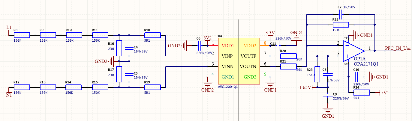
L1 and N1 are the input AC voltage-220VAC.
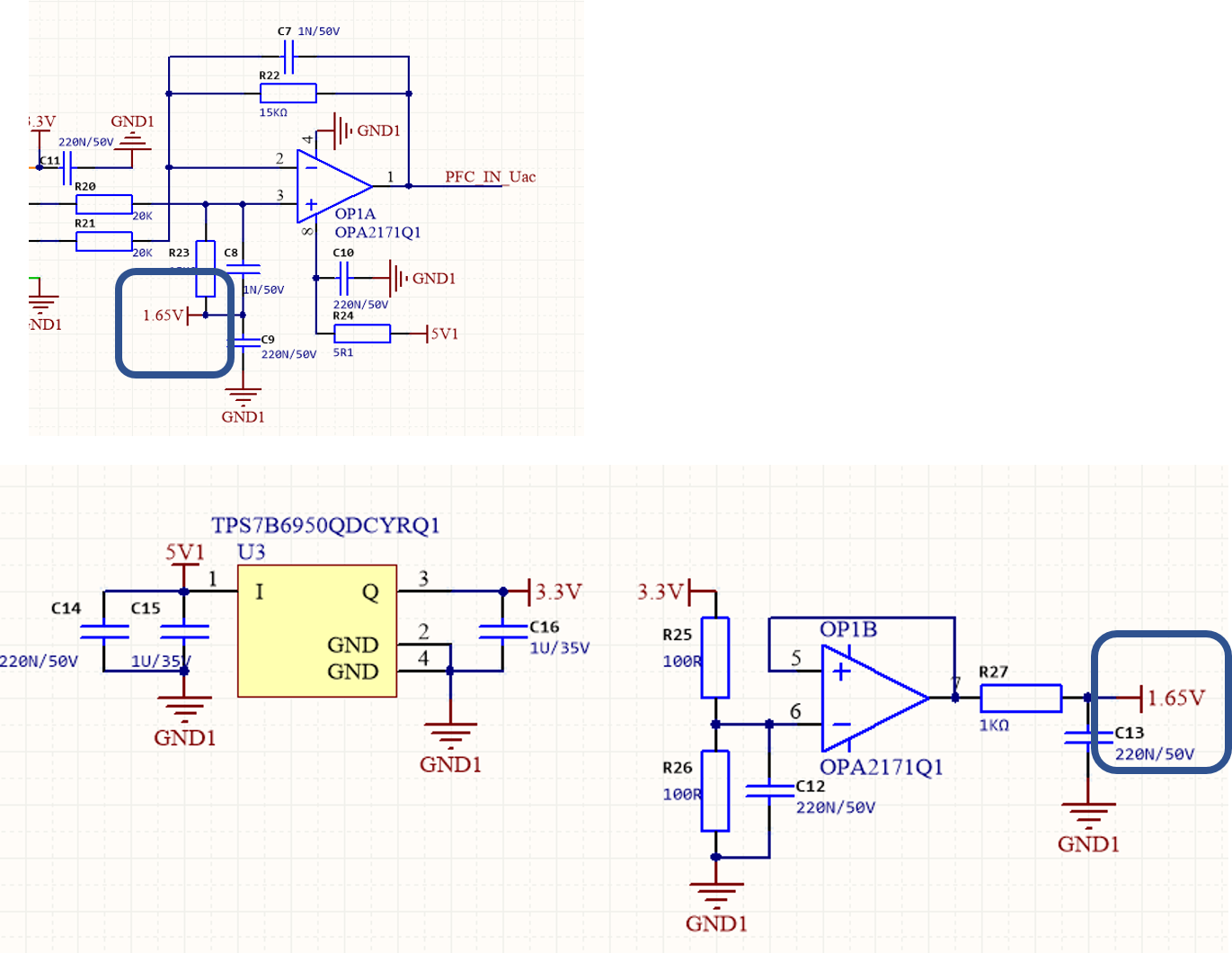
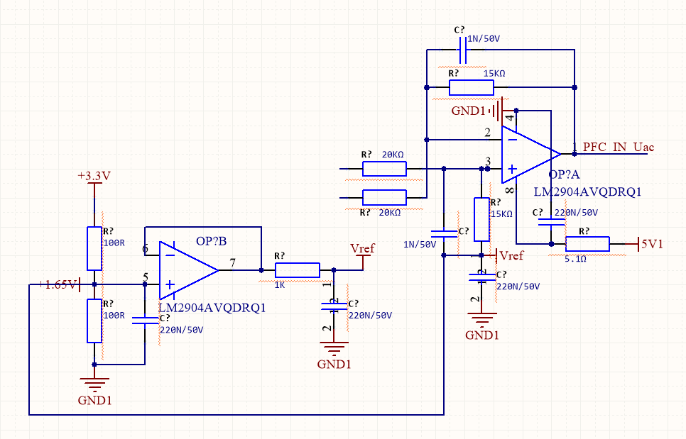
I acquire the voltage through AMC1200-Q1 ,then I amplify the diffirential signal through OPA2171 ->for PFC control
But when the AC Vin rised up to 200VAC (3kW),I increased the operating frequency of MOSFET which is in the LLC,not in PFC, the AC voltage signal PFC_IN_Uac had a DC offset.
I dont know why the sensed AC voltage signal had a DC offset, however I suspect that the increasement of frequency had an influece in it.
How should I design the AC voltage sample circuit?
Should I add an OPA in front of AMC1200 like the figure in www.ti.com.cn/.../tidrv40a.pdf
What is the reason the lead to the DC voltage bias?
Thank you again.
Good luck!