This thread has been locked.
If you have a related question, please click the "Ask a related question" button in the top right corner. The newly created question will be automatically linked to this question.
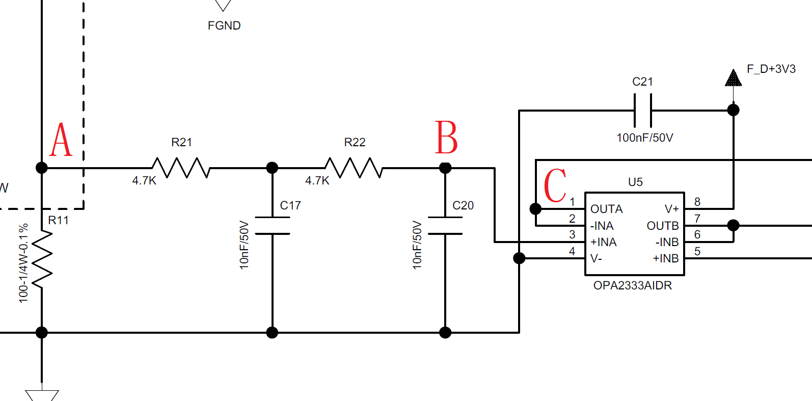
The circuit schematic is shown below.Using OPA2333 as a voltage follower. The conversion error is large, why?
FLUKE(754) test circuit at 30 ° C. UA=1V. UB = 0.9983V. UC = 0.9997V.
IB of OPA2333 is 200pA,IOS of OPA2333 is 400pA. Why UA-UB=1.7mV? Why UC is greater than UB?
Hi Rengui,
I already told you, that the OPA2333 cannot fully go down to 0V at its output. No OPAmp powered by a single supply can do this. There's always a dead zone of some tens of milivolt. But you could add a small negative supply voltage by the help of LM7705, or similar. Another method is to introduce a DC offset and to use the differential inputs of ADC.
Kai
Hi Thomas,
How is the conversion error of the OPA2333 in the circuit evaluated?
I know that the bias current and the bias voltage introduce an error. The bias voltage error in this circuit is 10μV and the bias current error is 1.68μV(200pA*9.8kΩ).
Looking at a piece of data before seeing noise and open-loop gain will introduce errors. How is this error evaluated?
Hello Rengui,
I have not seen the term conversion error applied to operational amplifiers, but what I think you are asking about is the total error observed at the OPA333 output due to voltage offset and input bias currents.
Rather than get into a lengthy explanation here about how each component I will refer you to the TI Precision Labs series:
Section 2. TI Precision Labs - Op Amps: Input Offset Voltage and Input Bias Current
You can access the session here:
The two sections require about a half-hour. You should have a good idea how to proceed in determining the total error after viewing them.
Regards, Thomas
Precision Amplifiers Applications Engineering