This thread has been locked.

If you have a related question, please click the "Ask a related question" button in the top right corner. The newly created question will be automatically linked to this question.

LM293: input sag at the output transition

Part Number: LM293
Other Parts Discussed in Thread: , TLV1702

Dear Specialists,

My customer is evaluating LM293A and has a question.

I would be grateful if you could advise.

---

When the output terminal (pin 7) goes from HIGH to LOW, a drop also occurs at the input terminal 5pin and 6 pin.

I'd like to know this phenomenon is due to the characteristics of LM293A?

Could you please see listed below.

Figure 1. Schematic

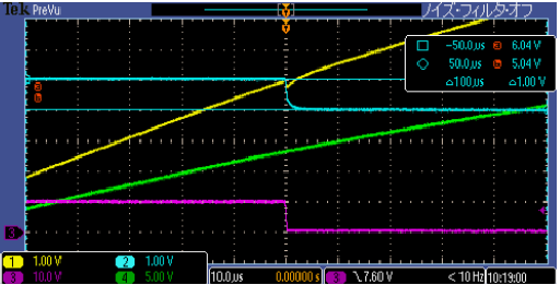
(1)When the output terminal (pin 7) goes from HIGH to LOW, a drop also occurs at the input terminal 6 pin.

Figure 2.

Time 10.0us/div

CH1(yellow): IC5-6pin, 1V/div, CH2(blue): IC5-5pin, 1V/div, CH4(green):CL8(VBAT_24V), 5V/div, CH3(pink): IC5-7pin, 10V/div

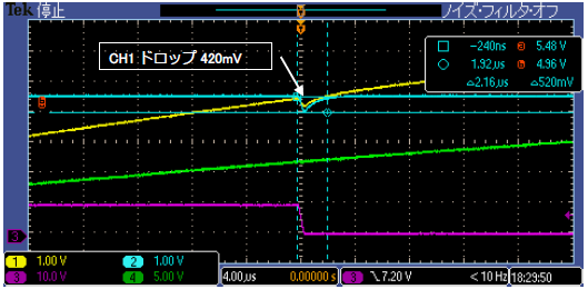
(2) And then removed R157 to confirm IC5-5pin, became without hysterisis, IC5-5pin also drop(420mV) at the output transition.

Figure 3.

Time 4.0us/div

CH1(yellow): IC5-6pin, 1V/div, CH2(blue): IC5-5pin, 1V/div, CH4(green):CL8(VBAT_24V), 5V/div, CH3(pink): IC5-7pin, 10V/div

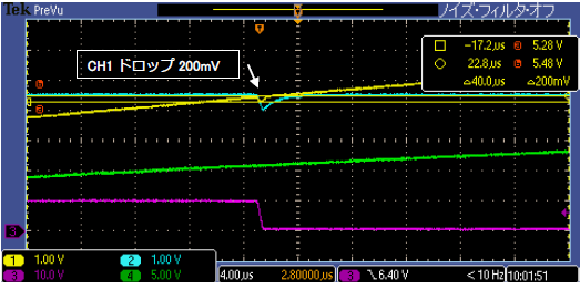
(3) When R59 is 200kohm to 20kohm and R62 is 100kohm to 10kohm, Voltage drop is reduced from 420mV to 200mV.

Figure 4.

Time 4.0us/div

CH1(yellow): IC5-6pin, 1V/div, CH2(blue): IC5-5pin, 1V/div, CH4(green):CL8(VBAT_24V), 5V/div, CH3(pink): IC5-7pin, 10V/div

(4) condition of (3) and R158 is 15kohm to 180kohm and add a 47kohm pulldown resistor at  IC5-7pin, voltage drop is more better from 200mV(result of (3)) to 120mV.

Figure 5.

Time 4.0us/div

CH1(yellow): IC5-6pin, 1V/div, CH2(blue): IC5-5pin, 1V/div, CH4(green):CL8(VBAT_24V), 5V/div, CH3(pink): IC5-7pin, 10V/div

---

I appreciate your great help in advance.

Best regards,

Shinichi

  • Hi Shinichi,

    the glitch can come from the gate source capacitance of MOSFET which discharges into the output of LM293. A gate resistor could decrease this effect.

    But thanks to the hysteresis this should not be a problem at all. This is what the hysteresis is used for, to stabilize the switching and make it immune to such glitches. So, I wouldn't remove the hysteresis. But why not connecting a cap from pin 6 to GND? This would decrease the glitch at this pin and furtherly stabilize the switching.

    Why are you posting this issue? Has any problem occured with this circuit?

    Kai

  • Hi Kai,

    Thank you for your reply.

    I am not thinking about the effect of MOSFET yet.
    As you mention, this phenomenon may be caused by FET and parasitic components.

    I'll ask the customer confirm by adding a gate resisitance.

    The reason of removing hysteresis is to clarify the problem.
    He doesn't intend to remove.

    The customer needs to report the reason of this glitch to end user.
    Firstly he requested me whether this phenomenon is due to IC.
    That is the background.

    Therefore I'd also like to respond from TI'er

    I appreciate your great help.

    Best regards,
    Shinichi
  • Hello Shinichi,

    The source impedance of the divider strings is fairly high, so the effects of a brief uA level pulses or capacitive coupling can be seen.

    You can test if it is the MOSFET by shorting the output to GND to keep it low (it will not harm the comparator - just be sure the device can handle that condition). If the glitch disappears, it could be due to transient currents, or, capacitive coupling between the input and output

    It could also be capacitive coupling between the output and the  negative input. They are right next to each other. The fast edge of the output (~200ns) is a high frequency transient that is easily coupled in through stray capacitence. Do the traces run along next to each other?Is any other signal moving

    If I simulate with 10pF between the negative input and output, which is not uncommon for PCB traces running near each other, I get a similar negative going glitch.

    It could also be a brief transient change in bias current due to the internal biasing currents changing during the transition time. The LM293 is an older bipolar device which uses PNP transistors in the input stage, so there is a measurable base current flowing out of the inputs. Try replacing it with a MOSFET input device, such as the TLV1702, and see if the glitch disappears.

    As Kai said, the "glitch" happens after the transition, so the hysteresis will prevent it from "back-tracking" - which is is supposed to do..

    If they are concerned about the "glitch", they can add a few pF (<100pF) across R62 to add some HF bypassing - but realize this will cause a slight delay.

  • Hi Paul,

    Thank you for your reply.

    I sent these information to the customer and confirm.

    As a result, it turned out to be due to the parasitic inductance of the lead wire added for measurement.

    Glitch noise disappeared when shortening the lead wire.

    The problem was solved completely.

    I appreciate your great help.

    Best regards,
    Shinichi