This thread has been locked.

If you have a related question, please click the "Ask a related question" button in the top right corner. The newly created question will be automatically linked to this question.

AFE031: datasheet formula error?

Part Number: AFE031

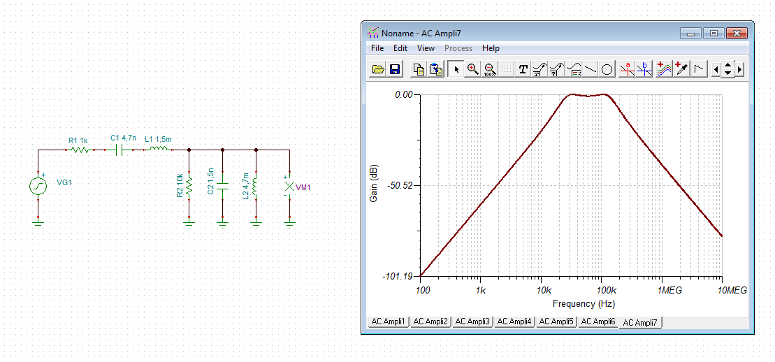
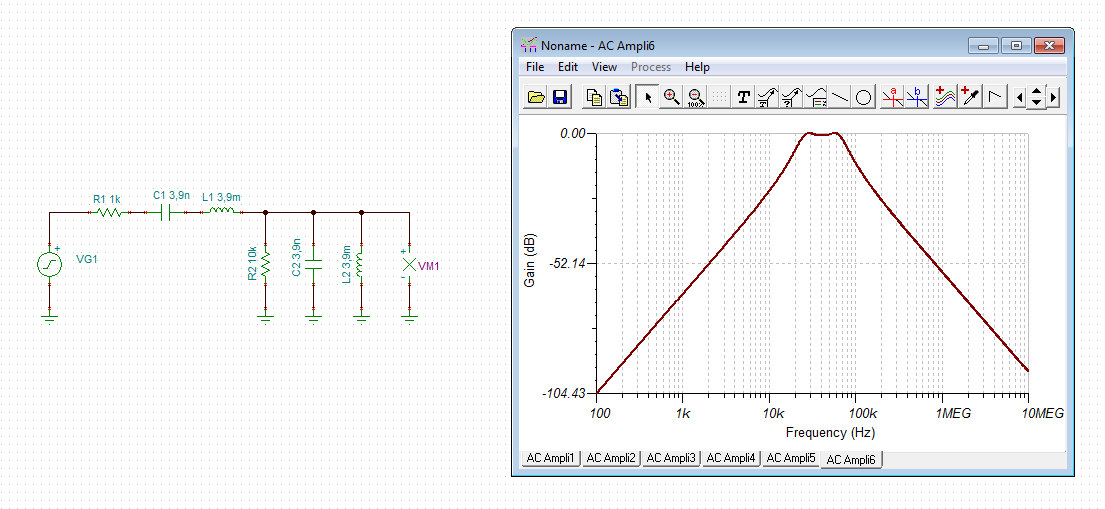
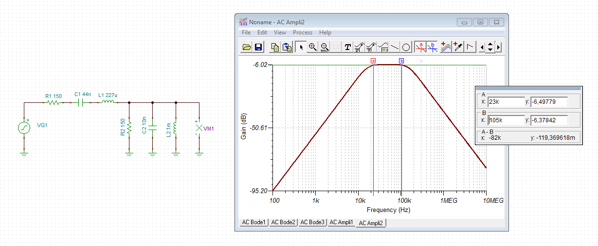
On page 27 of the AFE031 data sheet, the formula’s for determining the R, L and C’s are incorrect. My customer needs a 4rth order BPF with 0dB attenuation and a center frequency of 40kHz. 

Any guidance would be appreciated

Thanks

Viktorija

  • Hi Viktorija,

    I cannot see that the formulas are incorrect. If you set f1 = 35kHz and f2 = 95kHz for the "Cenelec A" band you get the band pass components values shown in table 4 of datasheet. The frequency response is quite useful:

    If you set f1 = f2 = 40kHz you will get the following curve:

    viktorija.TSC

    Kai

  • Hello Kai,
    Feedback from customer:
    There is a discrepancy in TI’s application note SBOA130A.

    I’m unable to get the same L’s and C’s shown in figure 6 on page 8 of SBOA130A with Zc=150, f1=24kHz and f2=105kHz using the equations

    Using these equations (equations on SBOA103A page 8 and data sheet page 27 are the same)
    a. With f1=24kHz, Zc=150 then C19 calculates to be 44nF.
    Figure 6 has C19=33nF?
    b. With f2=105kHz, Zc=150 then C20 calculates to be 10nF.
    Figure 6 has C20=22nF?
    c. With f2=105kHz, Zc=150 then L3 calculates to be 227uH.
    Figure 6 has L3=330uH?
    d. With f1=24kHz, Zc=150 then L4 calculates to be 1.036mH.
    Figure 6 has L4=470uH?
    e. Simulating using the calculated and/or nearest std. values yields f1=15kHz and f2=165kHz
    f. Simulating using the values shown on page 8 yields f1=23kHz and f2=105kHz

    How can I trust the equations when they don’t result in the values in figure 6 on page 8 of SDOA130A?

    Thanks
    Viktorija
  • Kai,
    Also - What exactly are f1 and f2 in your reply plot (f1=f2=40kHz)?
    On a band pass filter is f1 the high pass frequency -3dB point? Is f2 the low pass frequency -3dB point?
    Thanks
    Viktorija
  • Hi Viktrija,

    The equations in the Datasheet and Application Report are to used to compute specific LC component values. The implied intent here is to use the computed values to select capacitors that are readily available (e.g. 1.5 xF, 2.2 xF 3.3 xF, 4.7 xF, etc).

    As noted on top of page 27 of Datasheet, "The following steps can be used to quickly design the passive passband filter. (Note that these steps produce an approximate result)."

    The values in Figure 6 of the Application Report and Table 4 of the Datasheet reflect this component selection methodology: compute approximate component values, select readily available components and use simulation to finalize filter design.

    Also, while selecting actual components, please keep in mind that their tolerances may shift the center frequency and bandwidth of the filter.

    I hope this explanation helps.

    Regards, Neil
    Precision Amplifiers Applications Engineering
  • Hi Victorija,

    the filtering response of the bandpass filter of the application note is a bit sharper. The drop in frequency response at 23kHz and 105kHz is -3dB:

    The drop in frequency response of the "calculated" bandpass filter at 23kHz and 105kHz is only about -0.5dB:

    Yes, you are right, both filter components appear to be gained from different formulas. But, apart from the sharpness, the frequency responses are nearly identical.

    Kai

  • Victorija

    We haven't heard back from you so we assume this answered your question. If not just post another reply below.

    Thanks
    Dennis
  • Follow up question:

    We’re using OFDM carriers in the CENELEC band 23kH to 63kHz

    For AFE031 pins RX_C1 and RX_C2 the datasheet recommends using 680pf capacitors for a 90kHz low pass filter. What capacitors should I use if I wanted to get a 73kHz low pass filter?

    Thanks

    Viktorija

  • Hi Viktorija,

    Generally speaking, higher capacitor values will shift the low-pass cutoff frequency to the left (lower frequency). In this case, however, without having the complete (internal) LPF circuit available, changes to the external capacitor values cannot be easily simulated.

    Another consideration may be to adjust the cutoff frequency(s) of the recommended external bandpass filter, which can be simulated, to achieve the desired filtering of the incoming Rx signal. Again, as shown here in a TINA simulation, increasing the capacitor values of the bandpass filter presented in SBOA130A, has shifted the passband to the left.

  • Hi Victorija,

    Seems the image didn't insert properly into the previous post. Let's try again..