This thread has been locked.

If you have a related question, please click the "Ask a related question" button in the top right corner. The newly created question will be automatically linked to this question.

LM2907-N: Max Output Voltage isn't Outputted at Max Frequency

Part Number: LM2907-N

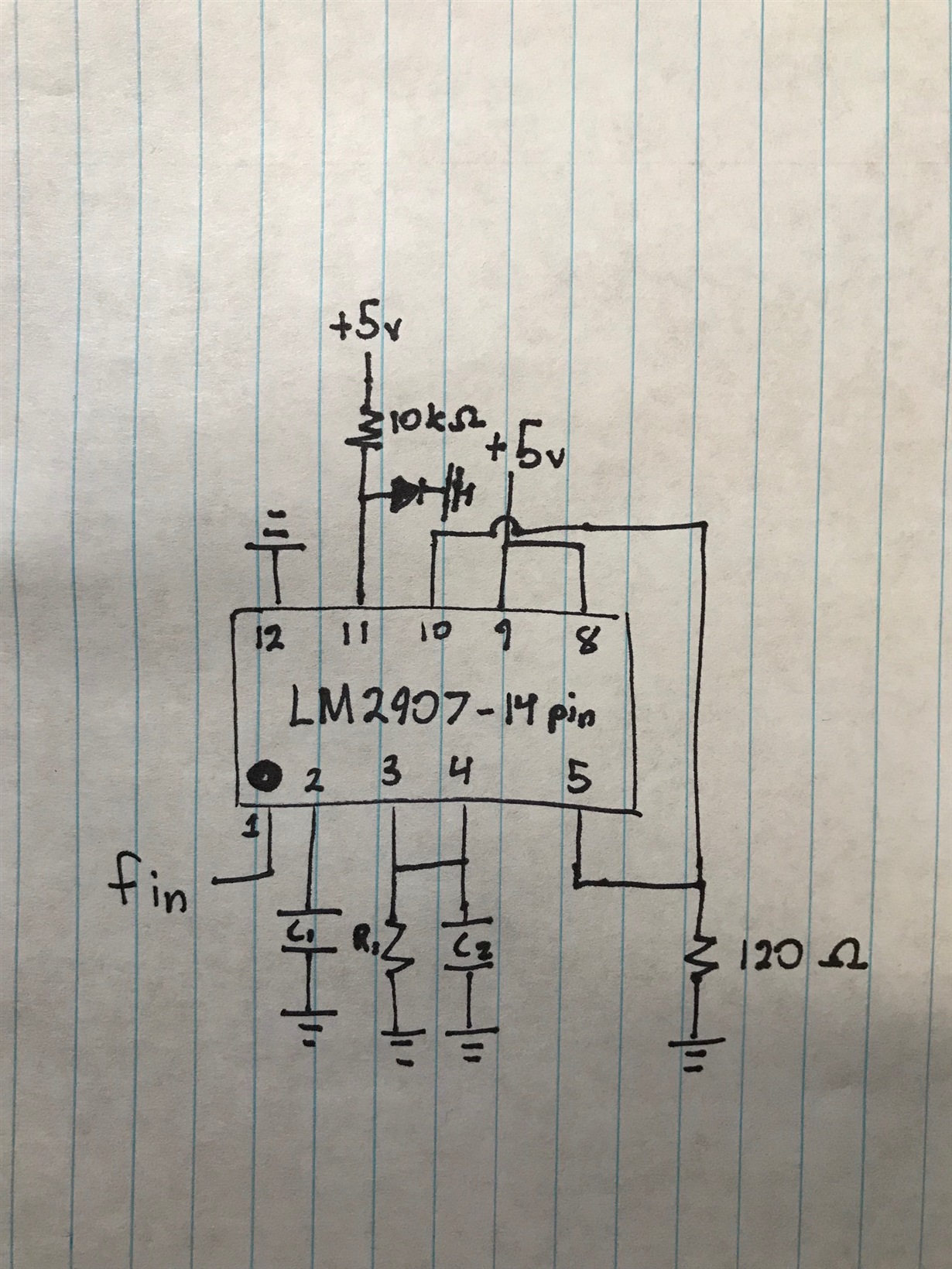
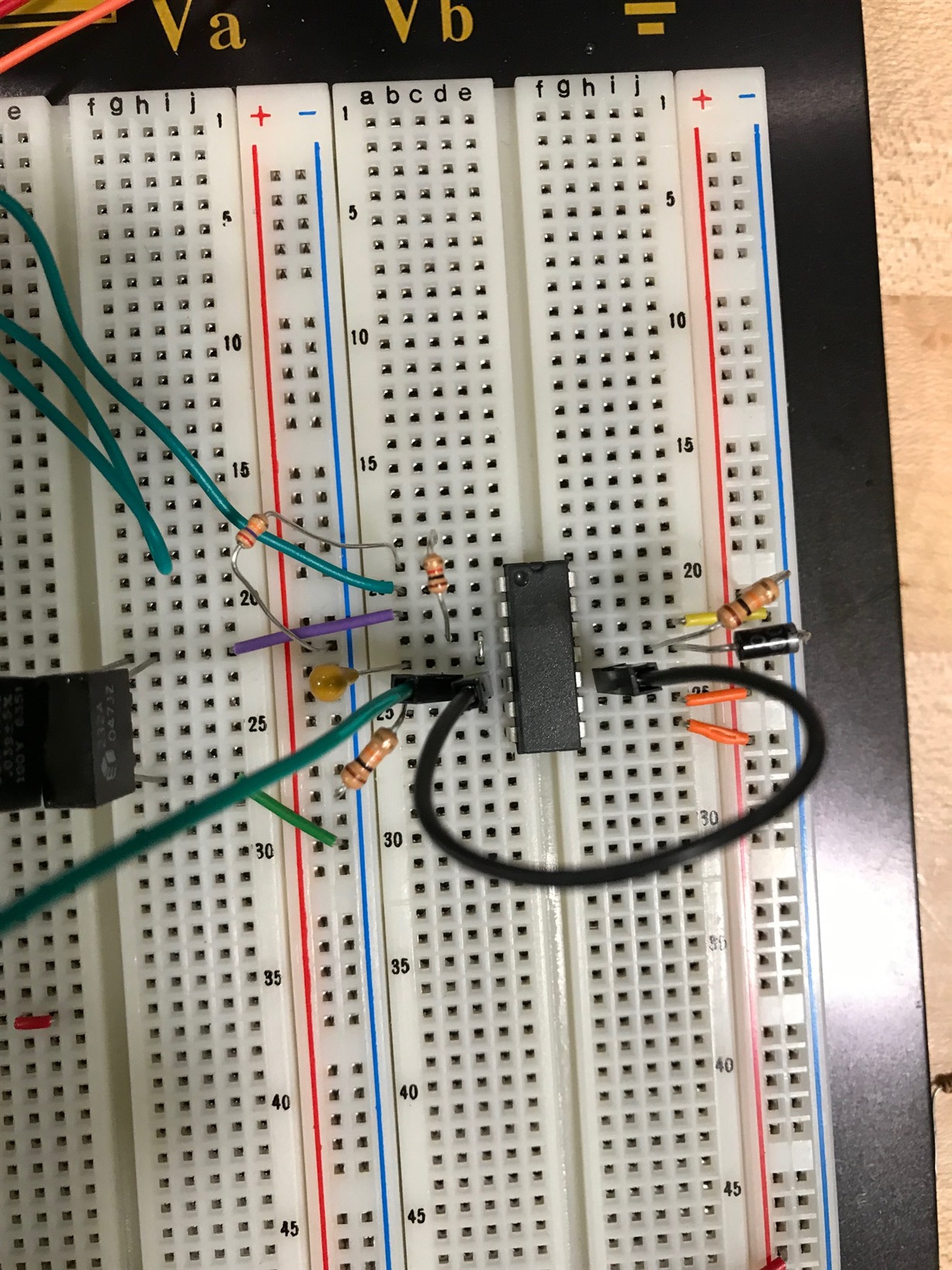
Hi TI forum, so I'm designing a circuit to take rpm and convert it into a voltage to be read by an Arduino. I have create a circuit using the lm2907 IC but when I use an input frequency of 420 hz the max oltage is only 3.62 V. When I did the calculations for R1 and C1 I used a max frequency of 420 hz and a max Vo of 5 V. I don't fully understand the equations for how to find R1, C1, and C2. My circuit does work because when I change the input frequency the output changes in value but never gets higher than 3.62 V. I will include a few pictures and a schematic to give a visual representation of my design. If you need any other details please ask because I would really like to figure out my problem so I can move forward in my development. Also this might not be super important but I'm a second year computer engineer so I might use incorrect terminology and I apologize for that. Thank you for any input!

I also used another forum post to attempt to fix my problems but it didn't make anything better. Link

Specifications

Vin = 5 v

Vout = 0-5v

My Calculated Values

C1 - 80 nF

R1 - 27,777 ohm (I'm using 28k because its close enough)

C2 - 1 uF (I choose this based on the example circuit given in the data sheet)

  • Hi Anthony,

    I would increase the supply voltage.

    And why is the resistance at pin 5 (120R) so small? I would increase it to 10k.

    Kai
  • The resistance was calculated by one of the equations that says the output current should be less than 50 mA at your input voltage. So I calculated the resistance to be ~100 ohms. I have tried changing it but it doesn't change my output voltage.

    I can try changing the input voltage but my system has a 12 volt supply and the arduino can only take 5v on the input. Can I have the output voltage be from 0-5v while the input is +12v?
  • Hi Anthony,

    the LM2907-N needs a minimum supply voltage of 6V. But it's better to have a bit more. So, just try a supply voltage of +12V and look what happens. Keep the arduino unconnected for this test. You can later reduce the output voltage by the help of a voltage divider.

    Make the LM2907-N work first. Modify it to fit the arduino in a second step. Divide and conquer!

    Kai

  • Ok, Ill try increasing the input voltage. I won't be able to test it until tomorrow so until then I'll recalculate the external component values and get back to you tomorrow. Thank you!
  • So I tested using 12 v for vcc. I recalculated the value for R1, RL, C1 and the new values are 67k ohm, 10k ohm, and 34 nF. When I tried the circuit the max Vo is 10.6 at max frequency. I'm lost now. I thinking I should be okay with less than 12 on the output. Is this normal for the lm2907?

  • Hi Anthony,

    yes, 10.6V is ok. Have a look at the functional block diagram in section 9.2 of datasheet: Between pin 9 and pin 5 there are two pn-junctions plus some other stuff. Makes at least 1.4V voltage drop. And 12V - 10.6V is also 1.4V. So, everything is fine. The LM2907 is a dino under the analog chips, designed at a time when nobody expected the chips providing rail-to-rail performance...

    Kai
  • If that is how it's designed then I can work with that. Is there a newer version of a chip that does frequency to voltage? If not then thank you for your help. It was much appreciated!