This thread has been locked.

If you have a related question, please click the "Ask a related question" button in the top right corner. The newly created question will be automatically linked to this question.

TINA/Spice/LMP7721: Gain curves-not correct

Part Number: LMP7721
Other Parts Discussed in Thread: TINA-TI,

Tool/software: TINA-TI or Spice Models

Hi ,

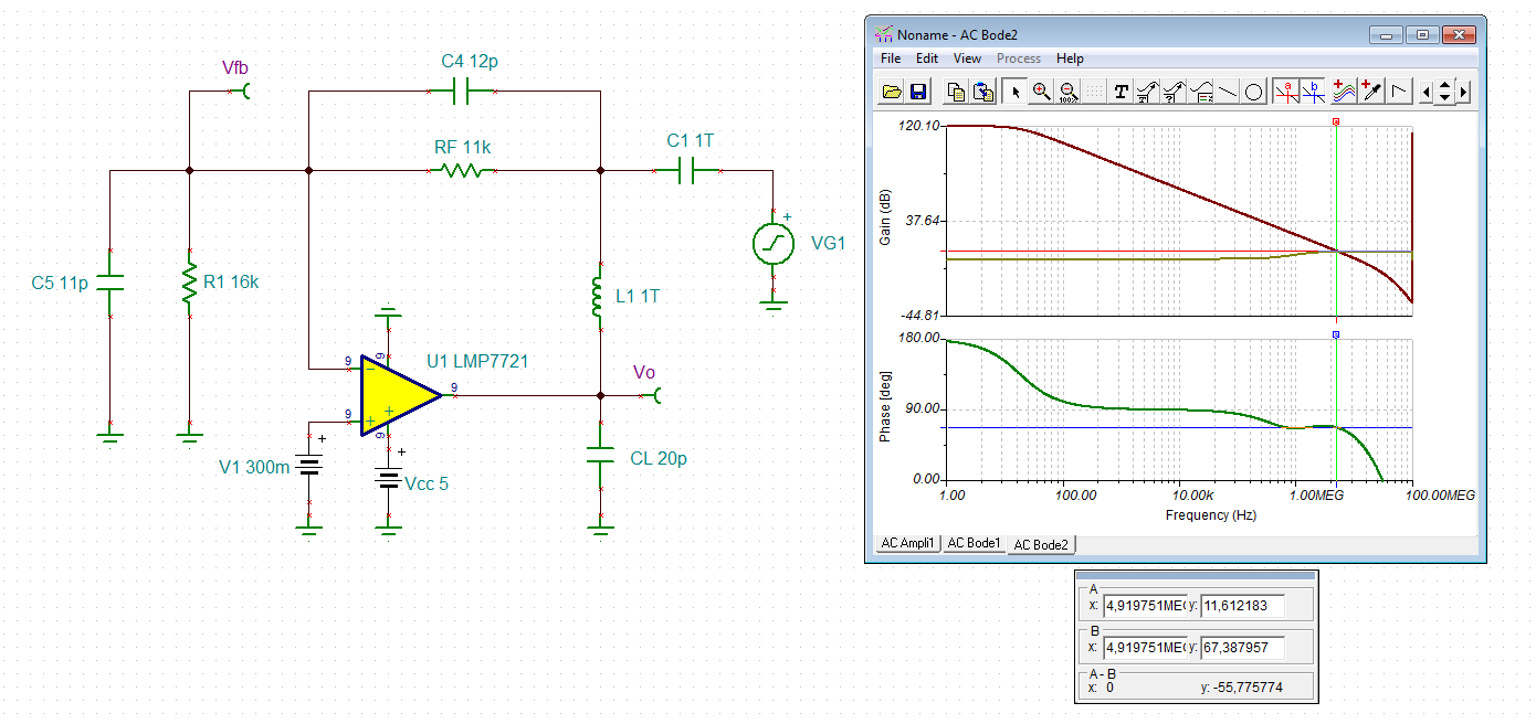
I am running some simulation to check phase margin, gain for my application for LMP7721 which I decided to use as Trans impedance amplifier for my application.

Below is what is my requirement:

BW=1MHz(min.)

Input current=400uA(max.) Output voltage=4.7V(max.)

Sensor resistor=16kohm

Sensor+ stray capacitance=1pF(max.)

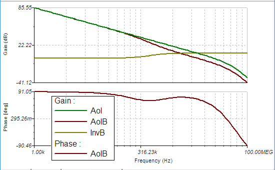
However, I don't see right open loop gain. Attached is my model and graph. Please let me know if I am running simulation right way(I did check out training videos from TI website) before implementing.

Also, did I calculated right parameters for feedback?

  • Hi,

    FYI, I will transfer this post to the product specific forum.

    Herman
  • Kai,

    I did check out video link mentioned above before implementing.

  • Kai,

    Thanks for doing this.But what if my input is mosfet based sensor.Does the resistance R1 still appears in parallel to Opamp ? I thought it would appear as I added in shared model above.
    Please advise.

    Regards,
    Sh
  • Hi Sh,

    I think the issue may be caused by the math you're using to create your curves. Using the following:   

    We can then define Aol as AolB/B. We'll also add a plot of 1/B to do a quick check of stability:

    the Aol curve generated here does appear to match the curve given in the LMP7721 datasheet. 

    The slope where 1/B (labeled InvB above) intersects with Aol with a ~20dB/decade rate of closure, which suggests that this design will be stable. The phase of Aol*B at the point where Aol*B reaches 0dB gives us the phase margin of the circuit: 65.5°, which again suggests that this design is stable. 

    I've attached my TINA-TI design below for reference. 

    TINA-TI Analysis

  • Hi Sh,

    what do you mean by "mosfet based sensor"? Can you give a link to the datasheet of this sensor?

    Kai
  • Kai,

    I don't have datasheet(custom part).But just consider it as a device which is based on MOSFET architecture. Current flows from source to drain (approx 400uA) with source being biased to 5V .Internal resistance between source and drain approx 16kohm with 400uA.

    How can I simulate this in TINA ?

    Sh
  • Hi Sh,

    can you at least show how this MOSFET is connected to your circuit? A schematic would be really helpful.

    And the 11pF stray capacitance is the drain source capacitance?

    Kai
  • Kai,

    This is initial research so we don't have final schematic We need to first test sensor with Trans impedance amplifier for performance check.

    11pF-Includes common mode caps of opamp(5pF),differential caps of Opamp(5pF),1pF sensor+ pcb capacitance

    Attached is the model how sensor would be connected. I just took standard part available in library as not sure if could actually simulate sensor. The gate of sensor will not be available.

  • Hi Sh,

    I think my Sh.TSC simulation shown above was pretty much perfect.

    Kai
  • i guys, there were a few points here I have been working on in some Planet Analog articles.

    1st of all, the LG sim approach being used is usually fine, but not as accurate as it could be. With all the effort recently put into open loop output impedance modeling, it seems odd to use an approach that isolates the feedback network from that Zol. It usually doesn't make much difference, but sometimes it does. Tried to describe this (and some transimpedance things) in this recent planet analog article.

    The way you are describing your sensor, maybe that 16k should be in parallel with the 1pF

    LG and closed loop look real good, discussion in this word file with TINA files below

    LMP7721 transimpedance question March2019.docx

    LMP7721 Zt LG.TSC

    LMP7721 11k transimpedance.TSC

    I looked again at the LG sim, and I had it wrong spot on the curve, actually a 62deg phase margin which makes more sense with the closed loop flatness. Also, a more reasonable shift down from the 65.6deg that Alex Davis reported using that older LG sim approach. So it only made 3.6deg difference in this case to do it the newer way - a lot of times it is not much differenceLMP7721 transimpedance question March3 2019 updated.docx. I put the updated plot into this word file, 

  • Hi Michael,

    Thanks for doing this and sharing useful information. However,I was not able to open "LMP7721 11k transimpedance.TSC" .Also have question about how is R3(99ohm) obtained in file "LMP7721 Zt LG.TSC".
  • So you were able to open the LG file? Yes, on that 99 ohm, at DC the inductor is a short - I have found in some of these sims if I add a small resistor to provide gain for the bias current to give a small DC offset it sometimes helps DC convergence - more so with the FDA's where I imbalance the two R's by 1 ohm. Once the AC run starts, the inductor opens up and the R dissappears with it. 

    I saved both files as V7 files, so it is odd you could open the LG but not the closed loop one - sorry, I don't know what else to do - the circuit is small, you can build it easily. 

  • Hi Michael,

    I have TINA-TI V9 and can also only open the first TSC-file.

    I have made the experience that TINA-TI cannot properly save more than one TSC-file per session sometimes. So, after the first TSC-file is saved, I close the TINA-TI session and start TINA-TI again from scratch.

    Kai

  • Thanks, so do I need to close TINA to add another file, or hit post and start  new post - I would hate to close TINA as I often have numerous files open

  • Hi Michael,

    I cannot say, what exactly is going wrong in TINA-TI. I can only say that TINA-TI acts weird from time to time. I give you an example. Yesterday I created a TSC-file to simulate the frequency response and step respsonse. When ready I saved the TSC-file with the "save as..." command. Then I modified the same TSC-file (without closing it or TINA-TI) to run a phase stability analysis. When ready I saved this TSC-file, too, again with the "save as..." command, of course, using a different file name. Afterwards I wanted to reopen the first TSC-file but it wasn't there. It totally disappeared as if I had never created and saved it. Such weird things happen all day long.

    It also happens to me that an attached TSC-file cannot be opened sometimes. Because of that I always check whether I can open the attached TSC-file.

    Can it have to do with that your file you wish to attach is sitting in a temporary folder?

    Kai