This thread has been locked.

If you have a related question, please click the "Ask a related question" button in the top right corner. The newly created question will be automatically linked to this question.

OPA189: Recommended for Photodiode Transimpedance Amplifier Application

Part Number: OPA189
Other Parts Discussed in Thread: OPA277, OPA2156, OPA2197, LMP7717

I'm looking into using the OPA189 for a transimpedance amplifier application.  I'm comparing it to the OPA277 (which is what the design uses now).  Looking at the specs, it seems like a great fit. 

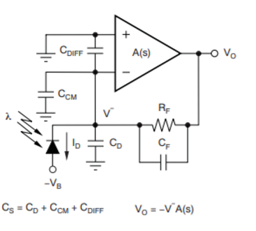
I wonder if the zero-drift / chopper architecture is recommended for TIA.  The literature says that the switching results in current pulses / charge injection.  And since the TIA will have a high value resistor (100k-1M), it seems like these charge injections might end up being noticeable in this application.  Please advise.  

Also, the chopper frequency is not listed in the datasheet, (although the datasheet does recommend using a passive LPF at the output.  What's the frequency range of the chopper?

  • Hello Rachel,

    Certainly a chopper Op amp can be applied in a transimpedance amplifier application, but higher performance may be achieved by other Op amp technologies.

    You state " The literature says that the switching results in current pulses / charge injection. And since the TIA will have a high value resistor (100k-1M), it seems like these charge injections might end up being noticeable in this application." 

    Indeed this can be a factor to consider in a TIA design. The input bias current is provided in some combination by the large resistance feedback resistor and the photodiode. During the time when chopping isn't occurring the input bias current is very low, typically tens of picoamps. However, when the switching occurs charge transfer also occurs causing the input current to momentarily spike higher. The current spike is very short in duration when compared to the entire switching cycle. Nonetheless, the current spikes flow through the feedback resistor/photodiode impedance and are converted to voltage that appears along with the desired signal at the Op amp output.

    One way to help reduce the effect would be to apply filtering to the chopper transimpedance amplifier. A capacitor can be added across the feedback resistor. Doing so will reduce the bandwidth of the amplifier. That may, or may not, be an acceptable compromise. The internal switching inside the OPA189 is at a couple hundred kilohertz and that is what be filtered. The cutoff frequency would need to much lower than a couple hundred kilohertz and that may be unacceptable if the photodiode input frequencies are in that range or higher.

    I expect an easier approach to achieving highest performance from a TIA would be to use an Op amp that doesn't utilize the chopper topology. For example, the OPA2156 is a new CMOS input Op amp having very low input bias current, ultra low noise and has wide bandwidth. It is easily applied as a high-performance TIA. Its datasheet provides an example of the OPA2156 configured as a differential photodiode transimpedance amplifier in Figure 46. You can find the OPA2156 datasheet here:

    http://www.ti.com/lit/ds/symlink/opa2156.pdf

    Another very good candidate for a TIA is the CMOS input OPA2197. It has voltage offset and drift that rival the chopper input Op amps, but do not employ chopping. The Op amps in this family utilize an electronic trimming technology to achieve the very low offset and drift. The datasheet can be found here:

    http://www.ti.com/lit/ds/symlink/opa2197.pdf

    I hope this helps.

    Regards, Thomas

    Precision Amplifiers Applications Engineering

  • Also Rachel, as you get further a transimpedance design you will find a decompensated VFA is preferred - more performance range vs quiescent power. The parts Tom mentions are extremely good wide supply range op amps. Normally, a TIA is not producing much output swing and the input does not move - if a 5V part will do, consider the LMP7717 also. 

    The compensation for stability is not hard, but critical - once you have your source capacitance and as much feedback R that you can get delivering the desired frequency span (higher gain BW product pulls that up), the simple way to set the feedback Cf for the transimpedance ckt shown here - 

    THis is an approximate, but pretty good equation - that Q sets the flatness - picking 0.707 will give a Butterworth. A lot of literature implicity picks a Q of 1 (without saying that) which gives about 2dB peaking and some overshoot and ringing. GBP is the true gain bandwidth product. 

  • Also Rachel, that LMP7717 is going to show up in a July article where I had built tables of decomp parts. The TINA model actually shows a true GBP of 109Mhz on that device - you would use that in Eq.1  in prior post,