This thread has been locked.

If you have a related question, please click the "Ask a related question" button in the top right corner. The newly created question will be automatically linked to this question.

WEBENCH® Tools/INA193: Eload Compensation

Part Number: INA193

Tool/software: WEBENCH® Design Tools

Hello Sir/Madam,

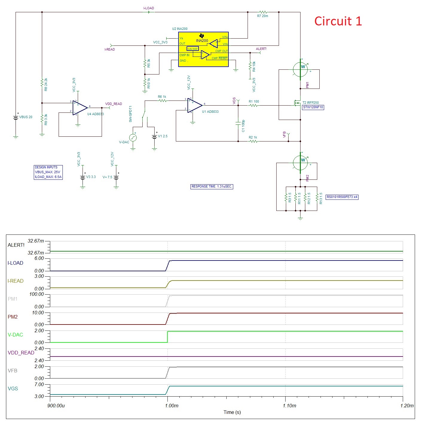
I am Designing an Eload. In Circuit 1, My feedback voltage is less. as my DAC output (V-DAC) varies from 0-2.5V Circuit works as per my expectations (No amplifier in feedback path).

But in Circuit 2, Since my DAC voltage goes to 5V. In order to reduce the power dissipation across R3, I used INA193 to convert that current to voltage and feed it to the U1. But when I run a transient response, I am getting oscillations. Can someone tell me how to compensate these oscillations with some feedback mechanism? (R12 &  C1) . Are there any calculations or formulas available to do this?

Please find my both circuits as well as simulations file.

ELODE final.TSCELODE Current to voltage.TSC


Vishal Kakade

Sr. Circuit Design Engineer | Hardware.

  • Hello Vishal,

    The INA193 is part of your feedback and this is placing the U1 device in an unstable condition.  There is set equation I have for you but please look at our precision labs training series for stability (See section 10).  This will help give insight on what is causing the issue and how you can approach the problem. I would in particular look at video number 3 in this section.  Please let me know if you need further assistance.

  • hello Javier,

    Thanks for your response. When I replaced C1 from 100pF to 100nF. It started working. I will look into the Video Series.

    Regards

    Vishal Kakade

  • Vishal,

    Good to hear that resolved your issue.  The videos will help with understanding it and will also help with making how much margin you have.

  • Hello Javier,

    I will explain the complete problem statement. Please tell me different ways to achieve it.

    Q. I wanna design an ELoad Circuit where-in, I should be able to set the current from 0A to 5A.(It should reach the set current within 15 to 20uS).

    The requirement is, there should not be any overshoot nor any Oscillations. We had different approaches like Setting current to 4.5A and then slowly increase it to 5A by reading current and adjusting the DAC voltage. But due to Response time mismatch, and delay in a feedback loop it is not possible.

    Can we design a compensation circuit similar to one in the Buck Converters wherein it compares feedback voltage and adjusts the PWM automatically, So instead of voltage, we should be able to do it for current in our application?

    Regards

    Vishal Kakade