This thread has been locked.

If you have a related question, please click the "Ask a related question" button in the top right corner. The newly created question will be automatically linked to this question.

PGA309: Multi-cal for the PGA309

Part Number: PGA309
Other Parts Discussed in Thread: XTR111

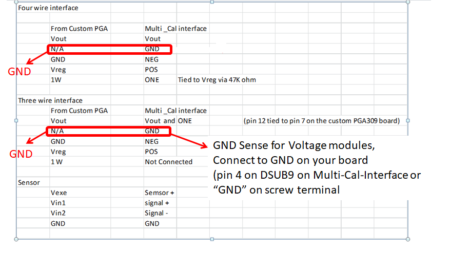
I am trying to use the multi-cal 309 system with my PGA 309 PCB design.  I am using it as a "3 wire" connection with the one wire connection.  I keep getting a communication error. I think I read the eeprom, although it does seem to be a default value.

Any help would be greatly appreciated. 

Thank you,

Steve

  • Hi Steve,

    Is it possible to get an schematic of the custom PGA309 board used on your set up?

    I will experiment with your hardware settings on the PGA309 multi-cal EVM.

    Thank you and Best Regards,

    Luis

  • Hi Steven,

    I will get a hold of the multical system, and expect to get back to you later this week.

    Thank you,

    Best Regards,

    Luis

  • Hi Steven,

    I went ahead and set up the PGA309 Multi-Cal system with the PGA309EVM Test PCB on the 3-wire configuration.

    On the PGA309EVM Test PCB board, I connected together the PGA309 Vout and PRG through the 'V2PRG' jumper as shown on the image below, with the device set up on the 3-wire configuration.  The PGA309 Vout and PRG need to connect together, and then they both need to connect to the Multi-Cal-Interface connector Jx pin 1 (One-Wire connection) and Jx pin 5 (Vout connection) on the Multi-Cal-Interface board. 

    I am not able to reproduce a communication issue, unless I purposely do not connect Multi-Cal-Interface board connector Jx pin 1 to Vout+PRG.

    Can you please let me know how are you connecting your custom PGA309 test board to the Multi-Cal-Interface board?  For reference, please find attached the pdf schematic of the PGA309EVM test board, and also please see below an image of the jumper settings removing the XTR111; and configuring the PGA309 on the 3-wire configuration on the test board.

    Many Thanks,

    Best Regards,

    Luis

    PGA309EVM_Test_PCB (muti-cal) schematic:

    PGA309EVM_TEST_PCB Schematic.pdf


  • That did resolve the communication issue.  Thank you!

    I am struggling with the calibration though. I try to calibrate my sensor but only I seem to only get a zero of ~2.4V and full scale of ~2.45V when I desire .5 to 3.5 V.  (sensor output is ~2mV/V and a zero of around 0.5 mV/V, my bridge resistance is 5K ohms).  I also see in the calibration window that vin min is listed as -91.192mV and Vin max is 148.5mV (which if that represents the raw sensor, that should not be).  

    So does VinMax/VinMin = raw sensor in the GUI?

    Sorry/ Thank you 

    Steve

  • Just to add some additional information, I connected the sensor via the PGA309 Test board and the sensor performed great.  That leads me to think there is something in my circuit, but I am not sure what it is. I thought I may have a common mode problem but it works on the PGA Test board.  

    Any help would be greatly apricated, we need to release this to production ASAP.

    Thanks,

    Steve

  • for a temporary fix, is there a spreadsheet I can use to calculate the calibration registers and than upload it through the USBEVM?  

  • Hi Steve,

    One possible concern from the hardware perspective is the bypass capacitor on the REFIN/REFOUT (pin 16).  The PGA309 user guide recommends to limit the bypass to 200pF or less (page 58 under AC considerations of PGA309 user guide). The PGA309 EVM multical  test board uses 100pF.  Can you please replace capacitor C3 with a 100pF capacitor?  The custom board schematic posted above shows C3=100nF.

    Unfortunately, we don't have a spreadsheet that calculates the calibration registers, the calibration is in general performed connecting the sensor to the PGA309 device, and the calibration process is performed using the multical system or PGA309EVM .

    - Please list all th connections from your custom PGA309 custom board to the Jx connector on the multical system.

    - Please share Pre/Post cal file that you are using on the multical system when using the PGA309 EVM multical test board,

    Please replace the REFIN/REFOUT capacitor (C3) with 100pF, and kindly let me know if issues persist.

    Thank you and Regards,

    Luis

  • Thank you!

    I ordered the cap, we didn't have one.  Please see the attached for cal files and configurations.

    Thank you, I truly appreciate your help.

    Steve/cfs-file/__key/communityserver-discussions-components-files/14/TI-PGA309-Up.zip

  • Hi Steve,

    Thank you for providing the information.

    Looking on the word document on the Multi-Cal-Interface connections to the Custom PGA309 test board, it appears one of the ground connections may be missing. The document shows you have correctly "Vneg" connected to the PGA309 test board GND, however, it appears the "GND" Sense connection for voltage modules may be missing. 

    Both, the "Vneg" and "GND" screw terminals of the Multi-Cal-Interface board need to connect to GND on your PGA309 Custom board on this case.  If you are using the DSBU9 Jx connector, these connections correspond to pin 3 (Vneg) and pin 4 (GND).

    Please see diagrams below (also refer to the "Multi-Cal-Interface User's Guide", SBOU093).

    Let me know if connecting the GND sense resolves the issue.

    Thank you and Regards,

    Luis


  • Hi,


    Connecting the GND did not make a difference. Although when I turn on the OWD flag, I get millivolt output. I also added the 100pF capacitor, which also did not make a difference. Is there something in the set-up that I may be doing wrong?


    Thanks,


    Steve

  • HI,

    I changed Vsj capacitor to 100 pF and the it seems to be working fine.

    Thank you for all the help,

    Steve

  • Hi Steve,

    That's good news. Thank you for letting us know,

    Kind Regards,

    Luis