This thread has been locked.

If you have a related question, please click the "Ask a related question" button in the top right corner. The newly created question will be automatically linked to this question.

TLV6001: Calculate resistor tolerance to meet the minimum CMRR

Part Number: TLV6001
Other Parts Discussed in Thread: TINA-TI

Hello, when i read the book <<Analog Engineer’s Circuit Cookbook: Amplifiers>> by TI at Page 23rd,

Q1: They said that Calculating resistor tolerance to meet the minimum CMRR at "Difference amplifier (subtractor) circuit"(see fig 1) by using the way in fig.2 and i do not know that formula came from?

Q2:I konw the CMRR=Aud/Auc, and Aud means the gain of different signal and Auc means gain of common mode signal. And in datasheet of OPA, CMRR= 20 x log(dVcm/dVos), and Vcm is common mode input and Vos means input offset voltage, and the value is internal parameter. But in fig1, the CMRR is NOT the CMRR= 20 x log(dVcm/dVos), and in fig.1 Vo=Aud x Vdiff + Auc x Vcm, and CMRR= Aud/Auc, which is not related to Vos caused by Vcm, and Aud and Auc is determined by External Rrsistor.

More, Vos is smaller than Vdiff (Vdiff=Vi2 - Vi1). So is it true that I say the different CMRR? and Why CMRR in fig.1 is not the parameter in OPA datasheet?

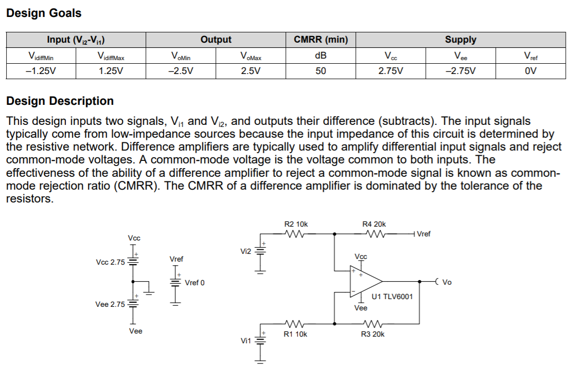
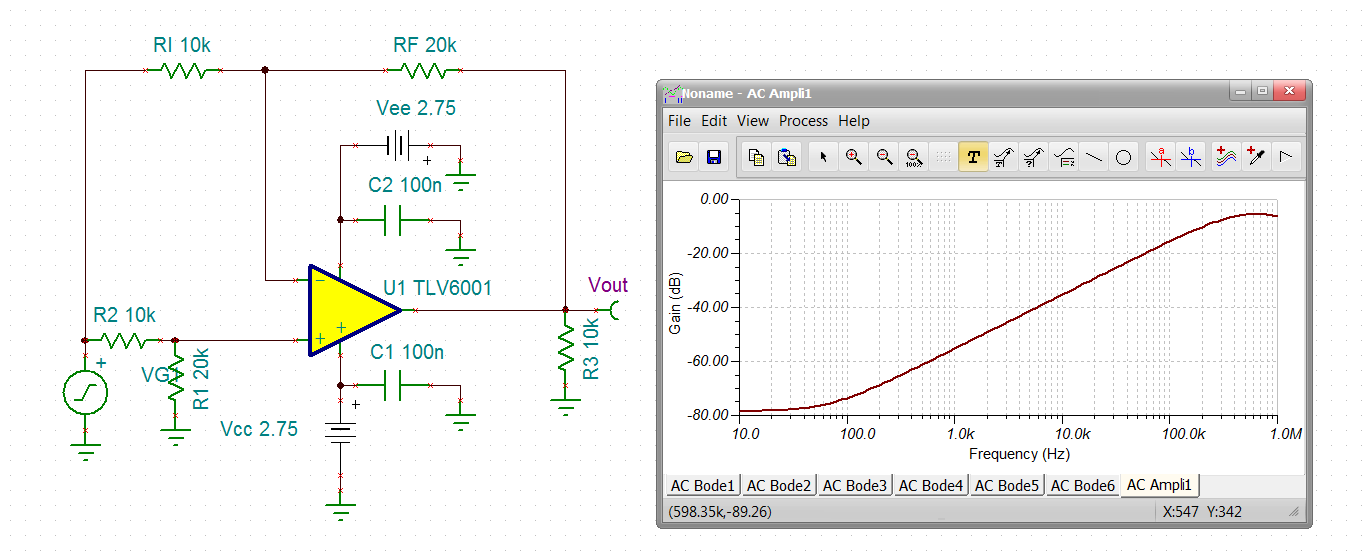
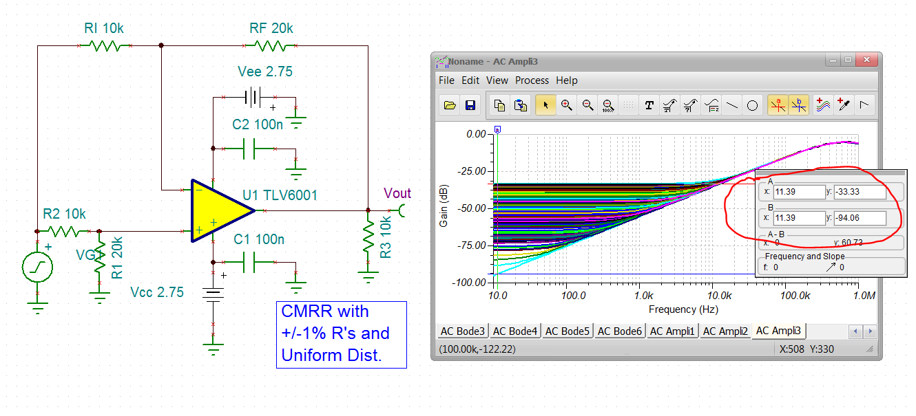
fig 1 Difference amplifier (subtractor) circuit

fig.2 calculation of the resistor

  • Hi Guooo,

    this is very simple and there's no need to use such a complex formula: As a rule of thumb, using four 1% toleranced resistors in the differential amplifier gives a total error or imbalance of about 1% (1/100) according to a CMRR of 40dB, irrespectively of how good the OPAmp is. Using 0.1% toleranced resistors yield about 60dB CMRR and 0.01% toleranced resistors give a CMRR of about 80dB. Furtherly decreasing the tolerance of resistors will hardly give an advantage, because varying longterm drifts and temperature drifts of the resistors will ruin the balance more and more. (If you need more precise results, run a TINA-TI simulation.)

    Highest CMRR can only be achieved, if all the four resistors of differential amplifier are collectively processed on the same die. So, TI's INAs, e.g., show an outstanding CMRR of up to 120dB and more! This would be entirely unachievable with a discrete design!!

    Kai

  • Hi kai,

    Thanks for your answer!

    Actually, I can calculate the resistor tolerance and CMRR by writing Vo=Aud x Vdiff + Auc x Vcm.

    I really want to konw how the reason of the forumla of the FIG.2 (in red frame)!

    Thanks!

  • Not sure where that equation came from, but we can do a quick monte carlo to prove results

    First, ideal gain of 2 diff amp CMRR shows pretty close to the specified op amp CMRR at 10Hz, 

    Then putting +/-1% tolerance on the 4 R's, uniform distribution with 500cases shows worst case. Essentially, that 1% would be 40dB but it is +/-1% so it is 34dB worst case, not sure where the slight degradation from that came from - maybe the op amp CMRR. 0.1% R's are not very expensive, but again that 60dB is reduced to 54dB worst case with the +/-0.1% variation. Eventually, all these curves hit the op amp's decreasing CMRR with frequency and ride on that curve. But, that is a nominal only curve with its own unspecified variation. I guess these are output referred rejections, drop by 6dB for input referred. 

  • Hi GUOOO,

    This equation is used on page 15 of +/-1A Single-Supply Low-Side Current Sensing Solution Reference Design. It looks like the document references a book written by Sergio Franco. Please see the References section of the document for the exact name and edition of the book. I do not have the book but I would believe this is a very reliable equation to use if it came from Sergio Franco.

    Thank you,

    Tim Claycomb

  • I have Franco's 2nd edition textbook, 

    This material is in section 2.4, difference amplifiers. I will check it out if I have time, 

  • Ok, I have spent some time in Franco's material - I think it is correct but hard to understand, 

    So the actual input referred imbalance error gain (<<1) is going to be the CM gain to the output then input referred by the signal gain. 

    To turn this around to a positive CMRR, reverse that division in this 20dB(Adm/Acm)

    That ratio cast in terms in of this epsilon does reduce to 20log((1+R2/R1)/epsilon). That 1+R2/R1 is the noise gain, makes sense

    But, that epsilon is the worst case imbalance - for +/-1% tolerance, that becomes .04

    So for the signal gain of 2 (noise gain of 3) the worst case CMRR is 20*log (3/.04) = 37.5dB (not very good). So if I take that monte carlo output worst case of -33.3 and input refer by the 6dB signal gain, that -39.3dB is not far off. 

    For a target CMRR due to resistor mismatch, take noise gain and then solve for epsilon, divide by 4 and that is your target % error on the R's. 

  • Hi Michael,

    Thank you for taking the time to look into this.

    -Tim Claycomb