Part Number: OPA858DSGEVM
Other Parts Discussed in Thread: OPA858,
Hi, an urgent help request.
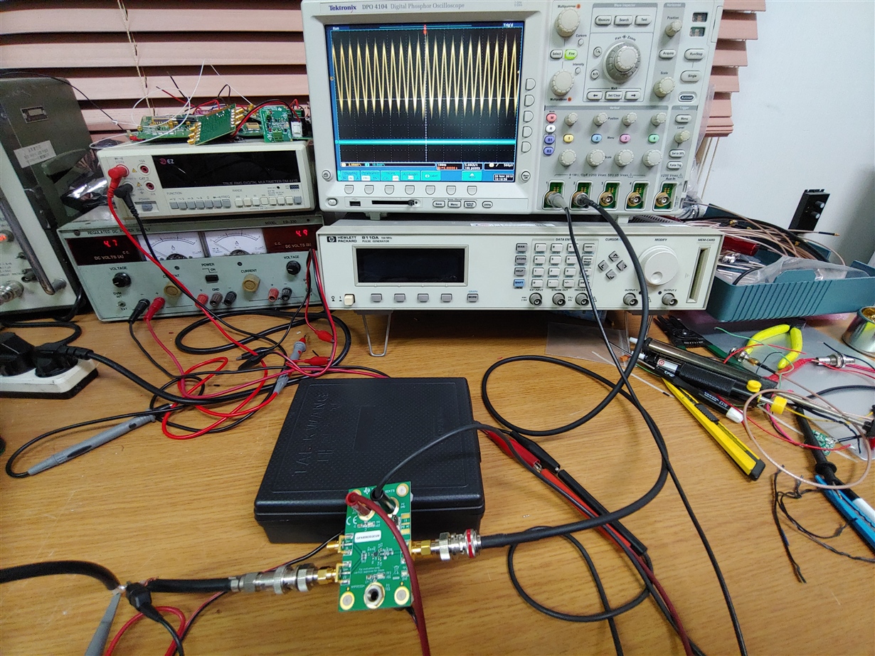
We have purchased an Evaluation Module for OPA858 amplifier, OPA858DSGEVM several days ago, and have tried
the module to test it for our OPA858 pulse amplification circuit design for our product.
However, the module doens not work at all. we have found the circuit uses R3 zero ohm resistor connected
in parallel with the differential input terminal to the ground. That means resistor R3 shorts out the RF input signalm and
consequently the module doe not output any siganl waveform to eh oscilloscope at the output connector.
Why did you short the input terrminal by R3. How can we test the moduel? Please explain the situation. Is it an mistake?
Do we have to remove the resistor R3, which is also very small and thus even very difficult to remove it.
Please give me immediate answer. I don't understandwhy this happened.
Regards,
Ki-Chang Lee
P.S. My collegue Iksoo Choi already have asked this matter to you on Friday. But still he did not get answer from TI.