This thread has been locked.

If you have a related question, please click the "Ask a related question" button in the top right corner. The newly created question will be automatically linked to this question.

OPA4196: OPA4196 & booster

Part Number: OPA4196
Other Parts Discussed in Thread: TINA-TI, OPA2990, TLE2071, TLE2141

Dear Michael, dear Thomas, thank you. 

Please, answer

I will use amplifier for the next purpose: I need to generate positive and negative pulses 5...14 V amplitude, 10....50 millisecons duration. 

1) Probably, you mean a distortion of the "step" type at the moment the voltage passes through zero? Please see figure 1 in attach.

Amplifier's harmonic distortion is not so important in my application.  The capacitance at the output of the amplifier, most likely, will not exceed 5nF.

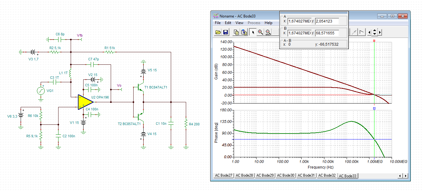
2) Based on this, can I apply my circuit without any modifications? Please, see attach.  Will I need a compensation to assure stability?

3) Does it make sense to install a 100 ohm resistor between the output of the amplifier and the bases of transistors T1 and T2 ?

TIA

Sincerely,

Vladimir Naumenkov

2860.Figure 1.docxOPA196 boost_3.TSC

  • Hi Vladimir,

    unfortunately, your circuit becomes unstable when the load resistance is increased. See how the phase margin gets eroded:

    At least a phase forward compensation cap should be added:

    vladimir_OPA196.TSC

    Kai

  • Dear Kai, thank you

    The fact is that I myself am a specialist in microcontroller programming. I work on circuit design because we do not have an expert in analog technology.

    Please, answer:

    1) How do you think, amplifier instability due to high load capacitance C1?

    2) What is the value of C3 and L1: "1T" ? 

    3) Inductance L1 should be removed from the final circuit? L1 only needed in the test circuit?

    TIA

    Sincerely,

    Vladinir Naumenkov

    www.agat.by

  • Those 1T L and C are just for LG simulation, you can't buy them, 

    HEre is what I mean by crossover distortion - this is 10kHz, the output pin has to jump 2 diodes to switch which output Q is active, that is a pretty nasty discontinuity and real ckts often oscillate there since the loop is open momentarily. You only need +/-70mA - plenty of op amps can do that, mainly main in higher speed, but you could still use them and not bother with the current boost. 

  • Hi Vladimir,

    I see no problem with a load capacitance of 10nF, provided you will add C7.

    C3 and L1 are part of the circuit simulation. The simulation method is called "phase stability analysis" and is very well explained in the "stability" trainings videos, especially part 3 and part 6:

    Kai

  • Dear Michael, thank you

    if I understand correctly, you suggest to use another oprational amp with a load of 200 Ohms in my application without a booster?

    Sincerely,

    Vladimir Naumenkov

    www.agat.by

  • Dear Kai, thank you

    Please, report, you made the Bode charts using the TINA-TI program? 

    Sincerely,

    Vladimir Naumenkov

    www.agat.by

  • Yes, if we had some more specs, could zero in - 

    1. speed

    2. care about DC precsion?

    3. care about noise?

  • Dear Michael, thank you

    I will use amplifier for the next purpose: I need to generate on the load positive and negative pulses 5...14 V amplitude, 10....50 milliseconds duration. 

    Honestly, I don't think, that speed, DC precision and noise is of particular importance in my application.

    0...3 V input signal will be supplied from the DAC. 

    And if I take a chip with a pair of transistors PNP and NPN (for booster), then the problem you described still remains?

    TIA

    Sincerely,

    Vladimir Naumenkov

  • Hi Vladimir,

    there's nothing wrong with using such a transistor booster. And if you want to decrease the crossover distortion, add a - let's say - 220R resistor between the base connection and the emitter connection.

    Of course, there are some better ways to build up such a transistor booster (-> class AB). But if crossover distortion, speed, DC precision and noise don't play a role in your application, then your circuit can do the job.

    Kai

  • Dear Kai, thank you

    Please, report, you made Bode charts using TINA-TI program?

    Sincerely,

    Vladimir

  • Morning Vladimir, 

    Your requirements are indeed modest except for that 14V/200ohm = 70mA output current. 

    The class B buffer you are trying to use may well work, normally I would never use it since 

    1. The LG file Kai sent is showing an operating point with the NPN turned on and the PNP off, that is one feedback state, the other is the PNP on, and the NPN off - a different state - 

    2. Can it be set to a zero output current mode - no, it can't - at minimum provide a pulldown R to the negative supply to shift the operation towards an NPN on bias. then, say you desired a true 0V output, then say a 10kohm to the negative supply keeps the NPN on closing the feedback loop. 

    3. there is essentially a deadzone of 2Vbe around zero, might not matter in your app. 

    I did look briefly for a higher V, slow op amps that can deliver >70mA (that can eliminate the class B buffer)  - there are a few, one interesting one just introduced, the OPA2990 (not sure if there is a single, looks like one is planned). You do need to provide some headroom for that 14V out, this one is RR out, but looking at the claw curve shows that 80mA is quoted is for sinking only, that is a little unfortunate, 

    Oh well, here are some other older ones to look at, you will need some >+/15V supplies to use this - you have a similar saturation issue on the class B buffer - at 14V output the base needs to sit at 14+Vbe, op amp needs to deliver that and the transistor need to not saturate at that Icc and Vbase. 

    TLE2071

    TLE2141

    And there are few others out there industrywide. 

    Good Luck, 

  • Dear Michael, good day!

    Thank you

    Please, see attach, I understand correct about additional resistors R3 and R8 ? vladimir_OPA196__work2.TSC

    Sincerely,

    Vladimir Naumenkov

  • Hi Vladimir,

    right now, I'm very busy in my job. So, I can't post here every day.

    Your R3 is fully enough. There's no need for R8.

    Kai

  • Dear Kai, Dear Michael, good day!

    Thank you

    I started a new thread because I thought that no one else would read this old.

    Excuse me, I have not clearly understand about additional resistor 10 k. 

    You wrote:  "2. Can it be set to a zero output current mode - no, it can't - at minimum provide a pulldown R to the negative supply to shift the operation towards an NPN on bias. then, say you desired a true 0V output, then say a 10kohm to the negative supply keeps the NPN on closing the feedback loop."

    Please, see attach, I understand correct connection of resistors R3 and R8 ?

    Sincerely,

    Vladimir Naumenkov

    7563.vladimir_OPA196__work2.TSC

  • Dear Kai, thank you

    I started a new thread because I thought, that no one else would read this old.

    I understood about resistors R3 and R8: R3 is fully enough. There's no need for R8.

    Vladimir Naumenkov

    www.agat.by

  • Hi Vladimir,

    does it work now with the booster?

    Kai