This thread has been locked.

If you have a related question, please click the "Ask a related question" button in the top right corner. The newly created question will be automatically linked to this question.

AMC1311: 250VAC / 400Hz isolated voltage measurement

Part Number: AMC1311
Other Parts Discussed in Thread: TLV9152, AMC1301, TLV9004, LMV324, OPA191

Hi,

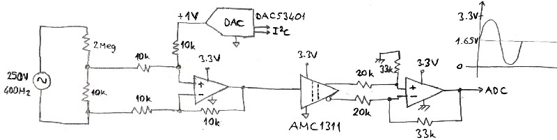
I want to design 250VAC/400Hz isolated voltage measurement as seen concept below.

Can I control 1V offset voltage by using a buffered DAC in that design?

Any recommend?

Thanks.

  • Hi Ali,

    This will work but I have a few comments. 

    1. Size of shunt resistor. Depending on what type of transients and range you would like to see, you may want to adjust this from 10k. In example, 8.03k would utilize the full-scale range of 0-2V for a 250Vac input. 

    2. The I2C lines for the DAC will need a digital isolator to communicate over the isolation barrier with the MCU. 

    3. The second opamp will need to be rail-rail compatible if using a 3.3V supply and expecting a 3.3V output. 

    4. If using a psuedo-differential ADC, you will also need 1.65V for the negative input, as shown here: http://www.ti.com/lit/an/sbaa317/sbaa317.pdf

    If using a single-ended ADC, disregard comment #5. 

  • Hi Alexander,

    Regarding to your comments;

    I've tried to make a simulation in spice by implementing AMC1311 spice model. ( Sorry not to use TINA :) I'm used to LTSpice. )

    I connected 1.65V ext.DC bias but can't get an expected output. It seems approx. 2.15V

    Second opamp is rail-to-rail but It 's not behave like first opamp.

    If done it, I will have a chance to use 1.65V-DAC reference at second side opamp without isolated. First opamp will has a regular DC bias.

    For comment 5 : Yes, using a single-ended ADC in MCU.

    Thanks.

    Ali

  • Hi Ali,

    Try adding a GND node to the low side :)

    Let me loop in someone from amps to suggest an alternative to OP191 as well. 

  • Former Member
    0 Former Member in reply to Alexander Smith

    Hello Ali and Alex,

    First, I would invite you to take a look at the following Texas Instruments Cookbook circuit document.  It highlights the design process for the circuit shown in stage 2 and I think you might find it useful.

    As for parts, I've put together the following list.  From left to right you'll go from lowest online price to highest online price.  Naturally, performance tends to get better as you move toward the right as well.  These parts are all "rail-to-rail output."  So, you may pick your part depending on how much precision you need.  The TLV9152 might be a good place to start, but I would verify that the output swing is sufficient for the application as you may want something that can get slightly closer to the rail.

    Regards,

    Daniel

  • Hi Alex,

    Tried add GND to low side :)

    I think that it is the same circuit in AMC1301 - Diff-to-Single Ended application note.

    But why not working? So confused :(

    Maybe, wrong GND measurement point?

    Attached Tina file.

    (OPA191 is not in my current design. Just, I needed any opamp in LTspice model for simulation. It will be TLV9004 or LMV324)

    Thanks.

    AMC1311_BipolarInputs_ali.TSC

  • Hi Ali,

    you have made a drawing mistake at V2. Now it works:

    ali_amc1311.TSC

    Kai

  • Thank you Kai!

    Hi Ali,

    I also made a mistake in the previous thread, the positive node of the opamp should actually be biased to GND, as you stated. 

    I was thinking of converting a +/-2V signal to 0-3.3V instead of 0-2V signal to 0-3.3V. 

    I apologize for the confusion, please let us know if you have additional questions. 

     ali_amc1311_Kai_AS.TSC

  • Hi Kai,

    Low AC signal at the input of  isolated opamp is swinging range in 0-2V on 1V DC bias. No problem until iso-amp.

    I had not seen AC signal output of second opamp in range 0-3.3V (rail-rail) on 1.65V (VDD/2) DC bias.

    Working with only single supply. So, I think I should choose optimal resistors to get x1.65 and should connect positive resistor to GND2.

    For example 20k-33k or 10k-16.5k etc...

    Now, no problem.

    Many thanks for your help. :)

    Ali