This thread has been locked.

If you have a related question, please click the "Ask a related question" button in the top right corner. The newly created question will be automatically linked to this question.

INA3221: Sensing voltage using current source

Part Number: INA3221
Other Parts Discussed in Thread: INA333, INA226

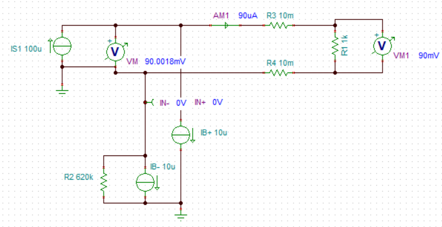
I understand voltage source (0-26V) is connected to IN+. This assumes a voltage source for the circuit. However my experiment deals with current source. A sample circuit diagram is provided wherein a current source is used and the idea with INA3221 as the Vm (voltage meter). My question is, can IN+ receive analog input from a current source (and not a voltage source as seen in datasheets)?

  • Hello Glenn,

    Thanks for posting your question to the forum.

    As noted in section 7.5 of the datasheet, the IN- pins have a 670kΩ input impedance from pin to ground and this resistance is what helping sense the bus voltage. So technically the IN- pins are responsible for sensing the input voltage, not the IN+ pins.

    I am not sure what your diagram is supposed to represent in relation to INA3221, but the device should be able to monitor the voltage of a current source. I believe you are asking if the device can monitor the voltage of a current controlled source and not a constant voltage source. The answer is still yes. If you have a constant current source, this will supply current to some load, which then will then raise the input voltage seen by IN- pin. The IN- pin will have minimal effect on the voltage since it is a high-input impedance pin.

    You can connect the INA3221 to the output of your current source just the same as if it was a constant-voltage source.

    If this does not help answer your question, then please post back any other questions.

    Best,

    Peter

  • Hello Peter:

    Well if you want me to get into the details here it is.

    The goal of my experiment is to analyze the resistance of the DUT (as seen in the diagram). I'm using the 2-wire test as based on the diagram. Using the equations, I can just simply isolate the resistance of DUT and solve it, but that assumes that I know the value of Vm. Vm is the measured voltage drop by the voltage meter.

    My idea is I want to use INA3221 as the voltage meter since that's the purpose of IN3221 ( to measure voltage drops). My problem is, from the looks of the INA3221 datasheet, it assumes a voltage source. My experiment deals with a current source, not a voltage source.

    My question to answer the problem is, can I still use IN3221 to measure the voltage drop if I use the current source?

    Source for diagram: https://www.edn.com/two-wire-vs-four-wire-resistance-measurements/

    Glenn

  • Hey Glenn,

    Yes. The INA3221 can measure small voltage drops across a shunt resistor, which is usually pretty small (<100-Ω). In your case, you are injecting a known current and determining the DUT resistance.

    Unfortunately there could be some problems with the input bias currents (IB) of the INA3221 depending on what the injection current is an what the input common-mode voltage floats to during the measurement. The IB for INA3221 at 12V VCM is 10uA (see datasheet). I would suggest running this in a simple SPICE simulation for all possible cases as shown below.

    If the relatively low input impedance of INA3221 (a current sense amplifier) introduces too much error, then consider using an instrumentation amplifier (e.g., INA333), which will most assuredly have a very high input impedance; however, it cannot operate on a voltage rail that exceeds its own supply voltage similarly to what the INA3221 and other current sense amplifier can do.

    Hope this helps.

    Best,

    Peter

  • Hello Peter:

    I was actually hoping to see the diagram look like this (see attached). 

    With: VOLT and VOLT2 as voltmeters and AMM as ammeter.

    Shouldn't this be the diagram while using the IN3221? VOLT2 is just a supplementary voltmeter for this visual purpose. But with this set up, I am hoping that INA3221 will supplant VOLT2 and take up the role of measuring the voltage drop. This is why the "XXX volts" is the voltage value INA3221 will give to me. In this case, "XXX volts" should be "1.706V."

    Am I interpreting things right? 

    From the looks of it, the input bias current isn't a problem since my target injection current is 9.5mA. This will most likely get higher in the future.

    P.S. R5 reflects the shunt resistor found between "power supply (0 - 26V)" and "load 1" in the image in the title page of datasheet.

  • Hey Glenn,

    You can certainly use the INA3221 as shown in the diagram you have provided; however, it will not report a voltage of 1.706V. 

    The INA3221 is a digital device and thus converts the shunt voltage into digital measurements stored in the shunt voltage registers.

    The INA3221 measures the voltage drop across R5 (the shunt resistor). So using Ohm's Law, VR5 (shunt voltage) = R5*I = 10mΩ*(9.5mA - 10µA) = 94.99µV. Unfortunately, this is going to yield massive error as the input offset of the device is specified at ±80µV max. You will want to increase the shunt resistor size and/or choose a device with less offset error in order to reduce offset error.

    Sincerely,

    Peter

  • Hello Peter:

    I see what it is going... I have checked your diagram you've sent and your explanation on the 3rd paragraph of your reply just. It seems that whatever load is in between IN+ and IN- is what IN3221 will analyze for its voltage drop. Is this correct?

    Correct me if I am wrong but, the way I understood the datasheet when I read it, was that "load 1" (see image from datasheet) is the load that INA3221 will analyze. This is how I interpreted it. I just assumed that the shunt resistor (in between IN+ and IN-) is a required component and assumed that "load 1" is the DUT.

    The way I understand it now is, the shunt resistor in the image is the DUT and "load 1" is simply unimportant in the calculation? Is this correct?

    Thank you for being patient in explaining these to me!

  • Hey Glenn,

    The INA3221 is a current-sense amplifier. So it measures current required by some load such as a motor, sensor, heater element, etc. 

    The device measures current by measuring the voltage drop across a small shunt resistor of known resistance chosen by designer. Current is calculated as Vshunt/Rshunt = I = "Load".

    Using the term DUT (device under test) is not really relevant in this sense. DUT is used to refer to a device/IC that is being characterized or measured.

    Consider watching out training videos to understand more about current-sense amplifiers.

    https://training.ti.com/ti-precision-labs-current-sense-amplifiers

    Best,

    Peter

  • Hello Peter:

    I am currently watching the current-sense amplifiers series. Thank you for that. Now, let's go back to the 1st diagram you've sent in this thread. I have remade it according to my circuit's specs as you can see below.

    Now in the diagram, I have "roughly", sketched-ly connected INA3221 to a microcontroller to do the voltage reading reporting. Ideally, based on our convo, "XXX volts" ought to reflect "2.489V" as this is the goal of my circuit (to measure the voltage drop of R2).

    The challenge in the future works of my experiment is that this R2's resistance will change through time. Of course as this changes, INA3221 will send the corresponding voltage drop reading at each time step to the microcontroller. This microcontroller in turn will create a record of voltage drops throughout the whole duration of the experiment. 

    I guess this is a clearer explanation of where my experiment is going to in the future.

    Your thoughts?

    Glenn

  • Hey Glenn,

    This latest design will not work. The INA3221 can only sense a full-scale range (FSR) of ±163.8 mV. This is shown in datasheet specifications table.

    Thus, differentially sensing 2.489V at the input will saturate the device and report to the MCU a shunt voltage reading of +163.8mV. Additionally, the bus voltage measurement (done with the IN- pin) will report 0V since it is connected to ground.

    If the point is to determine the resistance of R2 and I1 is a constant source, then I would insert back the shunt resistor to measure the current (11mA) as the part is intended. I would make sure the IN- pin is closest to R2 so that you can also measure the 2.489V drop, which will be reported as the "bus voltage" in the INA3221. Excluding errors from R1 and R3, you could calculate R2 a VBUS/I = 2.489V/11.12mA = 223.8Ω.

    There are definitely other ways to solve this problem. You could move the shunt resistor to the low-side so input bias current drops significantly and any offset in IB currents does not create an offset across R1 and R3. The INA226 is much more accurate and has a separate VBUS pin which you could connect to the high-side of R2 to sense 2.489V as the bus voltage.

    Hope this makes sense.

    Best,

    Peter

  • Hello Peter:

    Thank you for your suggestions! I have considered and even read INA226 datasheet, and I will stick to your suggestion of reinserting the shunt resistor and keeping IN- pin close to R2.

    I have another question tho. Since I will be using a current source to power my circuit, how can I solve the shunt current resolution? How can I solve its minimum and maximum current that it can handle? I'm assuming a shunt resistance of 0.01 ohms.

    I've been trying to calculate the latter but my results seem to contradict each other.

    Glenn

  • Hey Glenn,

    Determining the overall system resolution may require some testing, but the best case resolution will be the LSB of the shunt ADC which is 2.5µV. However, the current and resistor thermal noise could end up being larger than 2.5µV. Let' say that your shunt voltage noise is 4µV pk-pk. This means a 3µV change in the shunt voltage (3uV/R current change), may not be easily resolved by the device, at least instantaneously.

    Fortunately, you can use the customize the acquisition (or conversion) time of the signal and add differing levels of averaging to further clean up the signal. Se section 7.4.1 of datasheet for more information. Overall increasing the conversion time and averaging will reduce noise in the measurements, but slow down BW.

    I also highly recommend watching our TI Precision Labs training videos, specifically the ones about noise. This will show how to convert spectral noise density into peak-to-peak voltage values so you can understand the noise floor of your system. Consider researching the noise of the current source in you system.

    https://training.ti.com/ti-precision-labs-op-amps-noise-1?context=1139747-1139745-14685-1138803-13232

    Best,

    Peter