This thread has been locked.

If you have a related question, please click the "Ask a related question" button in the top right corner. The newly created question will be automatically linked to this question.

TLV7011: Zero Cross Detector-ZCD application

Part Number: TLV7011

Hello TI team,

I am working with TLV7011 for ZCD application but not getting the results.

I tried it number of times, it is blasting at very first switching but one time I got the results. It was also blasted after some time.

Kindly help me to resolve this problem.

One main thing, I have constructed the circuit as given in its data sheet for ZCD application.

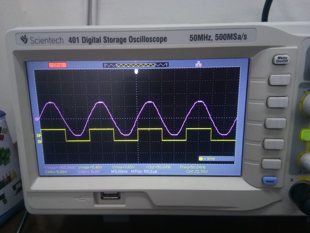
340 Vpeak (240 Vrms) is stepped down to 3.4 Vpeak through voltage divider and negative cycle is clip off by a zener diode (3.3V). 
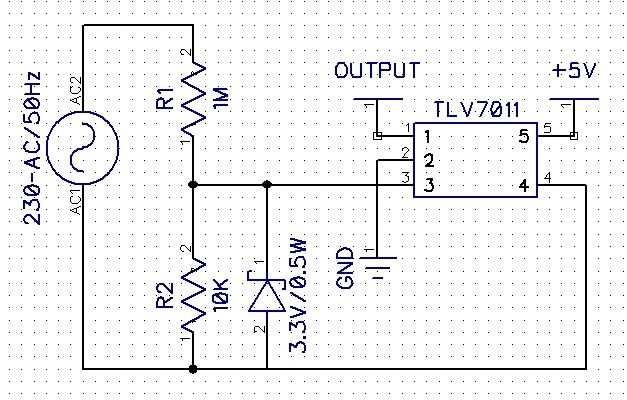
TLV7011_ZCD_Detector.pdf

I am attaching my schematic and output waveform.

  • Sayyed,

    STOP!  What you are doing is extremely dangerous.

    Are you connecting this to a live power line? Or through an isolation transformer?

    I can see what the issue is, but I am more concerned about your application safety.

    Before we continue, for safety, please answer the following questions:

    1. Is the 240VAC AC1 and AC2 coming from an isolation transformer? Or directly from the wall?

    2. Is the "GND" floating or grounded to safety ("Green") third-pin ground? Is your scope grounded to "green' ground?

    3. Can you provide a detailed schematic of the application and your setup?

  • Good morning,

    Paul Grohe Sir.
    Thank you for your reply. Answers are as below.
    Actually, I have constructed the circuit as per the given diagram
    1.Yes,It is coming from 240VAC live power directly no isolation transformer is used.
    2.GND is dc supply ground (Negative) which is coming from isolated dc supply (5V : Vcc and GND). Scope is connected with isolation transformer.
    3.I have already uploaded the schematic on E2E forum.
     
     
    Best regards,
    Sayyed Yaseen | Product Engineer
    Whitelion Incorporation.
  • Sayyed

    I would like to discuss with Paul his concerns on Monday.  In general, I am concerned about protecting the input of the comparator from negative voltage with a zener diode in a forward biased direction.  That will only limit the voltage to -0.7V which is beyond our abs max levels.  A preferred method would be to add another resistor in the string and have a standard diode limit the voltage to -0.7V at the first attenuation level and then have a 2nd resistor divider to limit the voltage to less than -0.3V.

    However, my biggest concern is that the zener diode in your circuit is not referenced to the comparator ground.  So any difference in ground potential can further increase the negative voltage seen by the comparator.

    We will get back to you with further application suggestions on Monday.

    Chuck

  • Hi Sayyed,

    I fully agree with Paul. There are several considerable mistakes in your setup and you should immediately stop your experiments!!!!!

    Mount your circuit at the secondary side of a mains transformer (safety transformer) and we will see how we can help you. But please stop experimenting directly with mains voltage :-)

    Kai

  • Hello Sayyed,

    First - TI can only give guidance on the comparator usage. The overall design and safety of the actual design is up to the customer. I would advise to seek council from someone familiar with designing off-line devices.

    The first thing is to NOT call ground "ground". That is what raised the red flags for me. "Grounding" a high voltage line is a bad thing.

    The "ground" you have now should be called "HV_COMMON", "FLOATING_COMMON" or something similar that does not infer ground.

    Floating test equipment is dangerous and is discouraged. .

    It is better to use the isolation transformer to "float" the test circuit and have a true safety ground.

    I will continue under the following understandings:

    1. The end circuit will be off-line powered with an isolated common (no "ground" connection).
    2. What you called "GND" I will call HV_COMMON, which is at the same potential as AC1
    3. FOR TESTING - The AC1 and AC2 come from a "floating" isolation transformer, such that AC1 can safely be grounded and the scope and ANY other test equipment are at ground.

    By schematic, I was referring to the complete schematic showing the line plug and load - basically - what are you trying to do?? The sim schematic is not detailed enough. I would rather help you find a safer way to do this...

  • There has been no update on this thread for a while, so I will be closing the post.

    If additional information is required, please reply to re-open or start a new post.

    Thanks

    Chuck