This thread has been locked.

If you have a related question, please click the "Ask a related question" button in the top right corner. The newly created question will be automatically linked to this question.

Current loop 0-20mA to 0-3.3V convert

Other Parts Discussed in Thread: INA186, RCV420, ADS1115, OPA333

Hi everyone, 

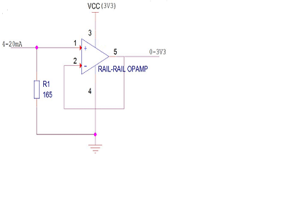
I have a Fiber optic amplifier which outputs analog 4-20mA current and I've low power controller and can accept upto 3.3V. I have used this readily available board to convert 4-20mA to 0.55-3.3V and then uses an ADC to read the value - https://it.aliexpress.com/item/32973712244.html

The module is noisy or needs to be re-calibrated again if the readings change at sensor side and it's not much effective for my commercial application. I am looking for something to develop inhouse and then use it. 

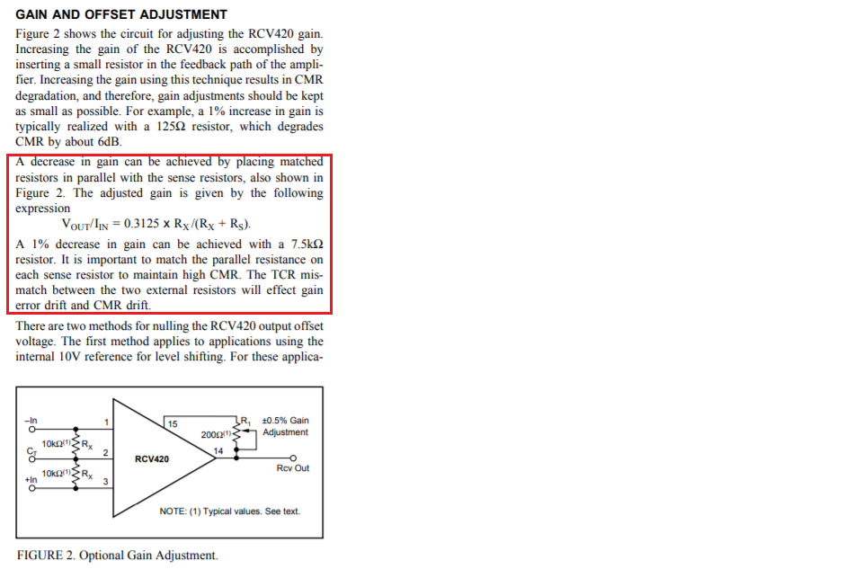
I have read about RCV420 it converts from 4-20mA to 0-5V. But my voltage range is somewhat different. I have read about connecting a resistor between CT and IN pin. Some people have suggested to use ina186 with discrete components. 

I am not sure about the circuits to use. Can you please help me to design the circuit or guide me? If you need more details, please let me know, I will definitely try to provide. 

I accept these kind of questions have been asked so many times on the forum but I still don't have clarity in my thoughts to implement. 

Thank you. 

  • Hi Krushna,

    Since you have 4-20mA current source, you want to convert up to 3.3V output in I-V conversion. You mentioned that you are familiar with convert 4-20mA to 0.55-3.3V conversion. Here is what you can do. 

    1. make sure that 4-20mA current source is referenced to ground. Some 4-20mA current source is floating, therefore it has to be connected differently. 

    2. If you want your upper voltage to be 3.0V for instance, your load resistor should be selected as 3.0V/20mA=150 Ohm for 20mA constant current. At 4mA, the output voltage is 4mA*150=0.6V. So your 4-20mA current source will generate 0.6V to 3.0V output across 150 Ohm resistor. since your A/D has a reference of 3.3V, this configuration will be pretty good to maximize the ADC resolution. 

    3. Connected 150Ohm between output of 4-20mA and ground. The output of 150 Ohm resistor will go to your A/D converter. 

    This is the simplest way to convert I-V. If you have something else in mind, please send us a schematic and we will be happy to assist you. 

    Best,

    Raymond

  • Hi Krushna,

    I forgot to mention that it will be better if you place a voltage buffer after step 3, before connecting it to A/D converter.  You do not get exact 0V at output. You will get 0.66V at the output when input current is 4mA, as shown in the circuit below. At 20mA input current, it will output 3.3V (you has to use rail to rail output amplifier, otherwise you will not get 3.3V at output). 

    RCV420 IC is a true differential current-to-voltage conversion, if you want convert 4-20mA to 0-3.3V exactly. 

    Method 2:

    If you want to use RCV420 , it converts from 4-20mA to 0-5V. You can use the IC to convert to 0-5V first, then  you have to use additional non-inverter op amp to convert 0-5V to 0-3.3 by reducing gain factor of 0.66 (3.3V/5V).

    Method 3: you may reduce the RCV420's gain by inserting Rx resistors at the input of the I-V converter. This will convert 4-20mA to 0-3.3V in the I-V application. 

    Vout/Iin=3.3V/16mA = 0.20625V/mA, see p.5 of the RCA420 datasheet. Then you calculate the Rx value through the following equation, see the attached image. You do not need addition op amp in this configuration. 

    0.20625 V/mA=0.3125 V/mA * Rx/(Rx+Rs), where Rs = 75 Ohm. And Rx is calculated to be: Rx=145.59 Ohm or  145.6 Ohm, which it has to be matching 1% resistors. 

    If you have any questions, please let us know.

    Best,

    Raymond

  • Dear Raymond, 

    Really Thank you for giving the reference to the designs and your guidance. I would like to go with method 1 using R-R Op-amp. But just few queries - 

    - Will it provide the precision accuracy at the voltage side when changing the value at the current side? For the reference, I will be using ADS1115 ADC converter. 

    -Which rail to rail Op-amp would you suggest for this application. 

    -What protections I can use in the circuit for Input protection at ADC, short circuit protections and ESD? - Series Resistors (~1K) at input end of Opamp will help from short circuit protection. 

  • Hi Krushna,

    Question:

    - Will it provide the precision accuracy at the voltage side when changing the value at the current side? For the reference, I will be using ADS1115 ADC converter. 

    -Which rail to rail Op-amp would you suggest for this application. 

    Answer:

    You may use OPA333 for the buffer, which is indicated in ADS1115. The OPA333 is low power, zero-drift op amp, rail-rail op amp, and is recommended to drive ADS115 in the datasheet. 

    Since you have constant source 4-20mA, your output voltage accuracy is determined by the accuracy of the resistor. Use 1% or precision resistor, say 165 Ohm, will do. If it is difficult to find 165Ohm precision resistor, you can parallel two 2*165=330 Ohm 1% resistors, which it will give you 0.5% precision. The Op Amp buffer will follow the input voltage and feed into ADS115. 

    If you want to input current protect OPA333, insert 5kOhm-10kOhm resistors at the input, see Figure 18 of OPA333 datasheet. You may not need it since this is Optical Fiber application. 

    Question:

    -What protections I can use in the circuit for Input protection at ADC, short circuit protections and ESD? - Series Resistors (~1K) at input end of Opamp will help from short circuit protection. 

    Answer:


    It looks like ADS115 has all these protection built in the IC, see the attached image below. 

    Best,

    Raymond

  • Hi Raymond, 

    I will give it a try with the suggested method & will provide you my results here. Thank you very much for your time and your guidance.