This thread has been locked.

If you have a related question, please click the "Ask a related question" button in the top right corner. The newly created question will be automatically linked to this question.

INA301: Questions about INA301 concerning BW and compression

Part Number: INA301
Other Parts Discussed in Thread: TINA-TI, INA3221, INA168, INA293, INA290

Hello,

I got another question regarding your INA301.

We've been comparing this device with the configurable INA325. The problem is that we need both configurability and bandwidth but the latter device is less performing in this sense.

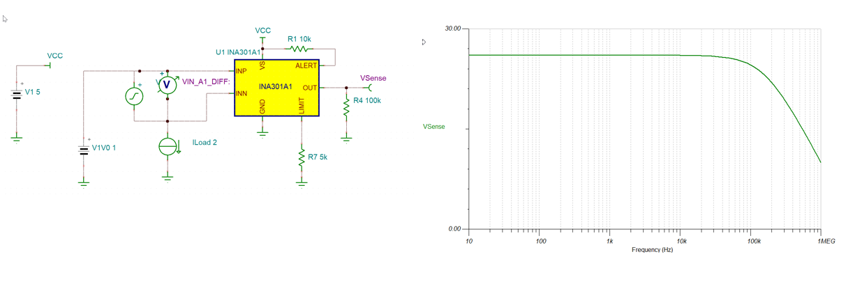
We've been simulating your device (INA301) with TINA-TI and, as expected, I noticed that for the High side sensing, with 1mOhm resistance the output is compressed and unresponsive until about 600mA.

I also expect a bandwidth around 500KHz, while I get about 150KHz, can you please explain why I get this result? (INP and INN) are correctly unbalanced with a few mv DC offset within the input source.

Here are my questions:

1. Can you suggest the best option for bandwidth, operational range (minimum working current) and gain configurability?

2. Can you explain the reason why we get such a low bandwidth?

3. By means of discrete opamp it is possible (when less precision is acceptable) to build a custom two stage CS which works down to a few mA of current by adding  and removing a given offset to both sages.

considering that we can scarify precision do you believe this is the best option in our case?, Can you propose a working discrete solution?

Best Regards,

GZ

  • Giulio,

    Please excuse the delay.  I am looking at this and will give you a reply today or tomorrow.

  • Giulio, 

    Could you please share the TINA file.  I tried my own simulations using the files on the INA301 product page and I have not been able to replicate the issue.

  • https://e2e.ti.com/cfs-file/__key/communityserver-discussions-components-files/14/INA301TI.7z

  • Cia Javier,

    In the previous message I uploaded the testbenches I'm using for bandwidth and compression evaluation.

    Thank you so much for your valuable support.

    BR

    Giulio

  • Giulio,

    I have some reasons for why the model is behaving this way.  The output is dealing with a lot of limitations at this point and all mus be overcome before the output is valid.  The biggest is output swing low.  The output will hit a saturation point and the max swing to low is 30mV.  I would not expect a linear response until the output is above 30mV ground.  This is also dependent on the load.

    You may also consider the offset of the device.  As well you may consider the input offset of the device that needs to be drive past before you get a valid output.   For your conditions and looking at worst case I see 125µV + CMRR(110µV) = 235µV Input offset.  CMRR = (12-1)*10µV/V= 110µV.   For the low side the swing low will dominate.

    As for the bandwidth I agree with you and we are looking into correcting the bandwidth of the device.  I will let you know when this is fixed.

  • thank you Javier

    We are actually comparing this solution ( sense amplifier + MCU'ADC) against  the INA3221. In our prototype they share with careful layout the same RSEnse. This is not optimal but allows us to make the idea about ups and downs of both solutions.

    We've been using INA3221 with great satisfactions for slow, less sensitive, supplies and we are trying this solution because it is inherently faster.

    Does INA3221 suffer the same limitations in the lowest current range? 

    Please let us know when the issue is fixed.

    Can you propose an additional solution (we are open to discrete opamps) capable to dealing with a broader range of currents?

    thanks for your support.

    BR

    G

  • Giulio,

    So the dynamic range you are looking for may be the biggest challenge.  One of our older devices has the bandwidth you need but the offset is larger and the bandwidth decreases with gain but since it was design a while ago it has an input offset of 1mV at room temp.  This is the INA168 which is a current out and you would need to change the resistance to change the gain.  Like I mentioned adding resistance (changing gain) will change your bandwidth.

    Our newer device can handle the speed you require but have issues with having adjustable gain.  Could you use two different gain options?  If that is an option you could look at the INA293.  If your common mode is above 1V you have in your simulation you could look at the INA290 which in preview status.

    If there are other design considerations please mention them.

  • Dear Javier,

    Unfortunately I am trying to monitor the current of a digital device in operational mode.

    This current can swing from a few mA up to 15-20A. we can also go below 1V..

    It's a very challenging task.

    I will definitely consider your other options with spice simulations.

    Meanwhile, please let me know when the model of INA301 is fixed.

    Regards,

    G.

  • Hello G,

    I have attached a TINA file with the model fixed for the INA301.  The web will be updated soon but here it is for your use.SBOM959_edited_model.TSC

  • Hi Javier

    Thank you so much:-))

    Regards

    G.