Because of the holidays, TI E2E™ design support forum responses will be delayed from Dec. 25 through Jan. 2. Thank you for your patience.

This thread has been locked.

If you have a related question, please click the "Ask a related question" button in the top right corner. The newly created question will be automatically linked to this question.

TLC2272: How to configure unused op amps in package for rail - rail single supply op amps.

Part Number: TLC2272
Other Parts Discussed in Thread: TLV2771, LM7705

I have read the various documents from earlier posts relating to this issue, such as

https://www.ti.com/lit/an/sloa277/sloa277.pdf  and https://e2e.ti.com/blogs_/archives/b/thesignal/archive/2012/11/27/the-unused-op-amp-what-to-do

  • Hi John,

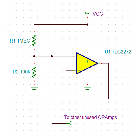
    I would do it this way:

    If supply current consumption isn't an issue in your application, I would decrease the resistors to 100k and 10k.

    Kai

  • Sorry my question seems to have been truncated.

    I have a TLC2272 and one half is configured as a single supply unity gain buffer.

    Its quite concievable that in normal operation, for much of the time, the non-inverting input (eg1+) will be at ground potential.

    As it is specified for single supply operation with a Vicr to and below 0V I'd expect it to work in those conditions.

    I would like to understand why the documents say connecting an UNUSED amplifier in the same way, with 2+ grounded is not recommended.

  • The blog says:

    Then connect the input to a voltage within its linear input and output range.

    For the TLC2272, VDD− is within its linear input and output range.

    However, a small offset voltage might force the opamp to try to lower its output slightly below VDD−.

  • Hi John,

    Clemens answered  your questions. 

    In addition, I found a relevant video "How to terminate an unused op amp", see the attached link. 

    https://www.youtube.com/watch?v=gwQiFuckMz0&t=4s

    If you have additional questions, please let us know.

    Best,

    Raymond

  • Thanks for your responses.

    a small offset voltage might force the opamp to try to lower its output slightly below VDD−.

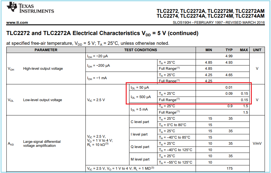
    Since its running single supply I dont see how it CAN. In fact the data sheet gives Vol (typ) = 10mV @ Iol=50uA

    So a "grounded" + input will inevitably be at a SLIGHTLY lower potential than the output pin.

    Also clearly there is the possibility of noise on the ground connection (emphasizing the benefit of seperate analog and digital grounds).

    However Vi(min) is listed as -0.3V and finding across a ground plane would be extremely unlikely.

    This app note www.ti.com/.../sloa039 

    shows a TLV2771 used as a non-inverting amplifier with a gain of 2 in a DAC. When Din = 0000 0000 Vref is 0V and Vo is (0V + a few mV).

    This is similar to my own application.

    So I'm really seeking an understanding, in relation to the internal operation of the op amp, as to why this "non-ideal" input condition of the + and - inputs being "different" is acceptable in this instance,

    but NOT acceptable for an unused op amp.

    Does it increase the power consumption of the device?  Or noise?

    Does it momentarily affecct the performance as components are released from saturation?

  • Hi John,

    you should allow the output of TLC2272 to swing to a level which is well away from output saturation. Because of this 0V may not be a good choice. Driving the output into saturation can mean an increase of supply current. Some other OPAmps can even show a drastical increase of supply current which would be a disaster in a battery powered application. Choosing an input and output level as I did in my example avoids to have to "invent the wheel" over and over again for every new OPAmp. So maybe the TLC2272 would even work with 0V. But I feel better to go no risk :-)

    Kai

  • Driving the output into saturation can mean an increase of supply current.

    So putting this simply, if you want to use a circuit where you expect input and output maximum excursions to be very close to Vcc (say 5V) & 0V 

    it would be MUCH better to power the op amps from (Vcc + a bit) and (0V - a bit).  (eg +8V -3V)

    That does make sense as its clearly impossible for the output of an active circuit to maintain a specified level (eg of 0V) with a changing load (eg Fig 15 of data sheet)

    UNLESS powered by voltages above and below that level. 

    Of course this has wider ramifications than just for unused sections of op amp packages.

  • Exactly, John :-)

    But as the OPAmps are becoming better and better over time, the necessary headroom also becomes smaller and smaller. Another option is to force the signals by the circuit design to be well within the supply rails.

    Kai

  • Thats not always possible, Kai; in my particular application I'm buffering the output from an ADC so the 0V is a requirement.

    I've concluded that there is no "proper" alternative than to use split supply; in which case the question of how to manage unused op amps in  a package becomes trivial -

    you configure as a unity gain buffer with the +input grounded (or grounded through a resistor).

    Thanks to everyone for their input

  • Hi John,

    Thats not always possible, Kai; in my particular application I'm buffering the output from an ADC so the 0V is a requirement.

    You might want to have a look at the LM7705 :-)

    Kai

  • Very interesting kai, -0.3V, just enough!