Other Parts Discussed in Thread: OPA657, OPA695, OPA830
Hiii
My photodiode current is very less (5Micro ampere to 10 micro ampere). So the standard transimpedance amplifier can't give the optimum performance since signal is mixing up with noise..
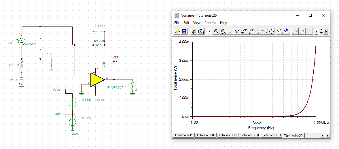
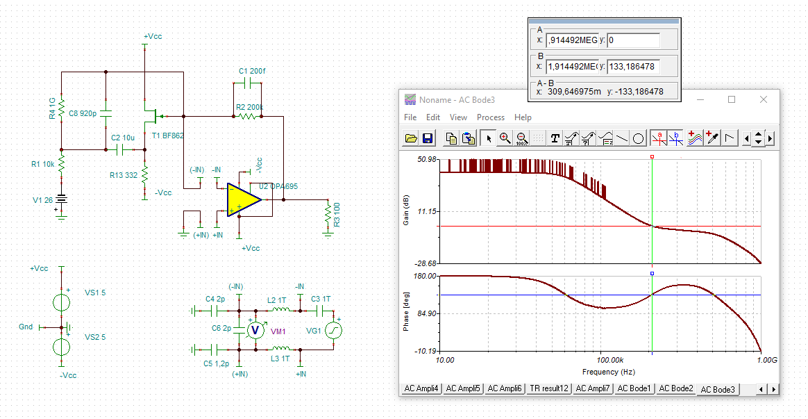
I came to know about Bootstrap technique. So I have designed simple bootstrap amplifier as shown below..
Theoritically at inverting terminal of OPA656 which is in feed back(buffer amp), should be virtually grounded since its non inverting terminal is directly connected to inverting terminal of other OPA656..
The voltage across capacitor 4.7UF should be Voltage across photodiode minus offset voltage of OPA 656 i.e, 25.75V theoritically..
But when I have connected this circuit on breadboard, at Inverting terminal of Buffer amp 4.4 V is observed. Observed Voltage across the capacitor is 21.6V.. 4.7UF/50V is used..
My photodiode capacitance is 920pF
Bias voltage applied is 26V..
Why OPA656 only??
- Due to its low input noise density: 7nV/root HZ.
- Also input capacitance is less around 3.5pF.
- Low input bias current 2pA..(since photodiode current is very low, bias current should be low).
Where I have gone wrong in the design?
Why the terminals are not getting virtually grounded?? what could be the reason?
Is there any other parameter that I have to consider while designing this type of circuit??
I would be grateful If I got the solution..
Thank you


