


Hi all,
I need to develop an analog-front end for some RTD sensors (PT100 and PT1000) .
I found two application notes (SNOA481A, SNOA838), which showns some practical solution usable to produce the reference current for an RTD sensor:
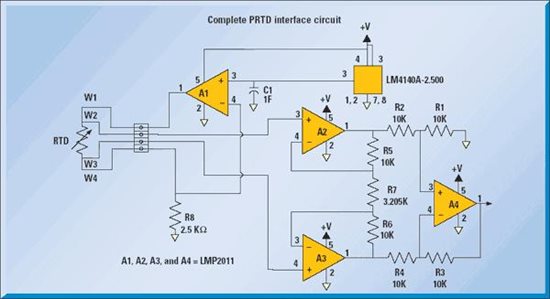
fig.1
this circuit uses only one opamp to generate the reference current. The excitation current is set according to the following equation:
Iref=Vref/R8
where Vref is the reference voltage at the output of the LM4140.
Another solution can be the following:
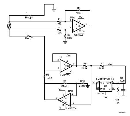
fig.2
In this circuit the reference current depends on the same equation shown above:
Iref=Vref/R8
but the following assumptions need to be true: R6=R7, R9=R10.
While in the circuit shown in fig.1 the current depends only from the resistor R8, in circuit shown in fig.2 the current depends from R8 and from the tollerances of the external resistors.
Thus, looking at the current source stage only, what are the benefits of this topology respect to the circuit shown in fig.1 ?
An Howland current pump circuit could be another possible solution ?
Thanks in advance


