This thread has been locked.

If you have a related question, please click the "Ask a related question" button in the top right corner. The newly created question will be automatically linked to this question.

Tl331 and suitable resistors value to form a square pulse out of it

Other Parts Discussed in Thread: LP2985, TL331

 I want to use/cut the output signal characterized as+-10V, 31 kHz, and dutyfactor  0.5 +-5-10% from the seconary side/ secondary coil of a Flyback topologie as a  5V controlsignal.The pulsewidth of the 5V control signal variable pulsewidth will be utilized for regulating/controling a servosystem consisting of CMOS. Today I use Zenerdiods( the last 5,1V)/ to cut the split of the output signal above down to around 5-6 V,but thereI get a no desireble minus voltage of 0.6V from the zener.
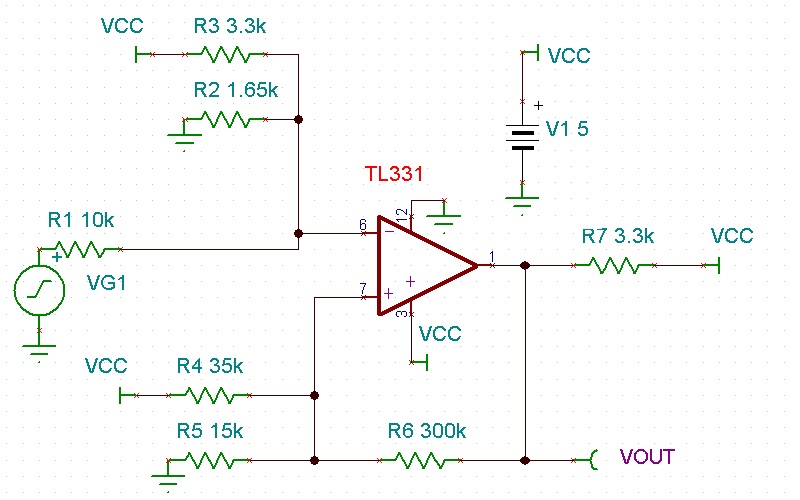
I want to use  an op. amp instead and think the TL331Q would do...Please give me a suggested connection scheme with suitable resistor value, and how I handle the earth and IN' and IN- . It's  fed from a +5V supply LP2985.


  • Christer,

    Do you want to convert a +/-10V signal to a +5V to 0V range or did I misunderstand the request?


  • Ron Michallick said:

    Christer,

    Do you want to convert a +/-10V signal to a +5V to 0V range or did I misunderstand the request?


    Yes,yes..to use it as a signal media as well of the incomining pulse which also produce power. I just want to use the variation in dutycyle(the width) of to pulse and feed into CMOS 5-6V devices (74HCxx)  for evaluation. I want to make it as fine/sharp  as possible ...I have used Schmitt trigger and zenerdiodes to 'clean' the pulse earlier to clean the shape of it to form square DC pulse of +5V in amplitude. The incoming pulse from the flyback could actually variate more than +-10V in amplitude. I use it's variation for other controlling purposes..

  • Yes,yes..to use it as a signal media as well of the incomining pulse which also produce power. I just want to use the variation in dutycyle(the width) of to pulse and feed into CMOS 5-6V devices (74HCxx)  for evaluation. I want to make it as fine/sharp  as possible ...I have used Schmitt trigger and zenerdiodes to 'clean' the pulse earlier to clean the shape of it to form square DC pulse of +5V in amplitude. The incoming pulse from the flyback could actually variate more than +-10V in amplitude. I use it's variation for other controlling purposes..

  • Yes,yes..to use it as a signal media as well of the incomining pulse which also produce power. I just want to use the variation in dutycyle(the width) of to pulse and feed into CMOS 5-6V devices (74HCxx)  for evaluation in servocontrol device. I want to make it as fine/sharp  as possible ...I have used Schmitt trigger and zenerdiodes to 'clean' the pulse earlier to clean the shape of it to form square DC pulse of +5V in amplitude. The incoming pulse from the flyback could actually variate more than +-10V in amplitude. I use it's variation for other controlling purposes..

  • Christer,

    I attached a circuit that should work well provided that the TL331 is fast enough.

    Resistors R1-R3 convert +/-10V to 1.5V +/-1V. The attenuation supports up to +/-15V input.
    There is a 1.5V bias on the non-inverting input with some hysteresis.

  • Christer,

    I noticed that you did mention the frequency in the first post. The TL331 will be fast enough.


  • Thank you Ron... I appreciate the work and circuit , impressive. I will have a closer look, but I will say that when I see yours I can understand my problem to get the TL311 work properly myself. Please if possible in few words explain why one need to 'bound in the op' so hard within a lot of Vcc. conections.

    Say I would like to double the supply Voltage from to day 12-15V , how to  handle that? First do you think the TL311Q will be a good choice, or overkill? Say the autobile branch/inustri go for 24V instead of  12V ...

  • Sorry...it's late now.  Bad spelling in last answer and of course I mean TL331Q  the variant of TL331 for harder environment..With Supply Voltage I mean the +- amplitude of the voltage  of the pulses coming from the coil of the flyback, not the Vcc +5V supply, it remains.

  • Christer,

    Chose the the TL331 that covers your temperature range needs.

    The circuit changes the amplitude of your input range (gain/attenuation) and changes the center voltage of range (offset). The reason is to make sure the common mode range of the TL331 is met. I chose 1.5V because it is the center of 0V and VCC-2V.

    On the TL331, the common mode input voltage is actually the input pin with the lowest voltage (most negative, least positive). Only one input needs to be in the common mode range, the other input can go as high as 30V. If any input goes negative then the current must be limited and the output may be invalid.

    I attached a spreadsheet that I use to find a trio of resistors to change one input range +/-X to a new range. Change only the yellow cells.

    3 Resistor divider with DC offset (do not lose).xls