This thread has been locked.

If you have a related question, please click the "Ask a related question" button in the top right corner. The newly created question will be automatically linked to this question.

OPA4171-Q1: Output stage equivalent circuit

Part Number: OPA4171-Q1
Other Parts Discussed in Thread: OPA4171

Hi team,

My customer uses OPA4171-Q1. They have a leakage current test like below,

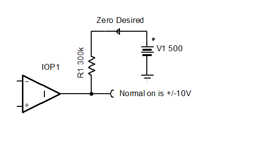
500V power supply->300k Resistor->VOUT of OPA4171. They find the leakage current will be 1~2mA. But this is not allowed in their system. Could you kindly help provide:

1) the equivalent circuit for output stage of OPA4171. And explain the theory of the current.

2) Do you have any suggestion to select another opamp to reduce the current?  Output needs to be +/-10V. Ib <=OPA4171's Ib.  No GBW requirement.

Best Regards

Michael

  • Micheal,

    Are you really saying that the output of the opamp must tolerate 500V without drawing any current?

  • Micheal,

    Most CMOS op amps (including OPA4171) have this output.

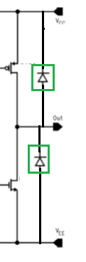
    Drain output; PMOS on top, NMOS on bottom. Drain to backgate makes diodes seen in green boxes.

  • Hi Ron,

    Thanks for your reply. Is it possible to select a BJT or other process based opamp without this clamping diode? 

    Or do you have any other idea to work around it?

    Regards

    Michael Huang

    FAE

  • Micheal,

    There are other devices but none can tolerate 500V.
    If you have 500V though a 300k resistor to output pin and no current flows then both sides of resistor have 500V.
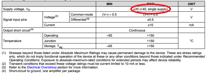
  • The reverse-biased diodes shown in the diagram above are part of ESD protection scheme and are present on all I/O pins regardless of the process technology used to implement the circuit.  For that reason, in the case of the output voltage being driven to 500V, the current must be limited to 10mA or less by adding a series output resistor to avoid damaging the ESD structure.  Therefore, the only way to limit the output current further is to use a higher series output resistor.  However, please be aware that LDO regulators cannot sink current and thus if you use LDO as your supply voltage in order to limit the current to 10mA or less you must add TVS or Zener diodes as shown on the ESD/EOS schematic below.  Without it, the supply voltage would be pulled up above its Absolute Maximum Rated voltage of 40V resulting in permanent damage to the part.

    For more detailed information about ESD/EOS protection, please watch the series of TI Precision Labs videos under the followinglink:

  • Hi Marek and all,

    Thanks for your suggestions. I think I have known your thoughts. If the current is low enough with 300k resistor, the voltage at VOUT will be 500V-I*300k, which is large enough that may break the circuit inside.

    I will talk with customer to check if they can change this resistor to meet their requirement.

    Regards

    Michael Huang

    FAE

  • Micheal,

    There is a misunderstanding or the customer is requesting the impossible.

    You asked for a normal +/-10V output and no current through a 300k resistor.

    This is directly conflicts with Ohms Law. Just remove the 300k resistor and the problem will be solved. 


  • Ron,

    This is a new design for them. I have ask them to use a larger resistor here to reduce the leakage current.
    They didn't use a opamp here before, so they have this issue this time. If you want to talk about details, we can communicate by mails. Thanks!

    Regards
    Michael