This thread has been locked.

If you have a related question, please click the "Ask a related question" button in the top right corner. The newly created question will be automatically linked to this question.

OPA564: Amplifier Clipping Well Below Supply Rails

Part Number: OPA564
Other Parts Discussed in Thread: OPA561, TINA-TI

Hi,

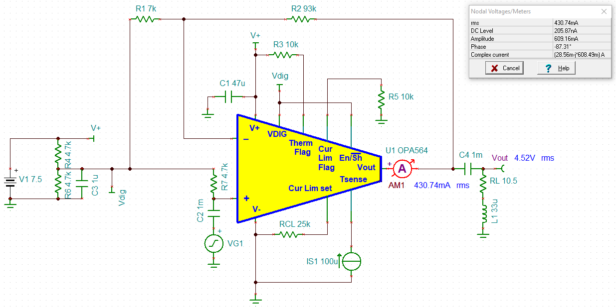
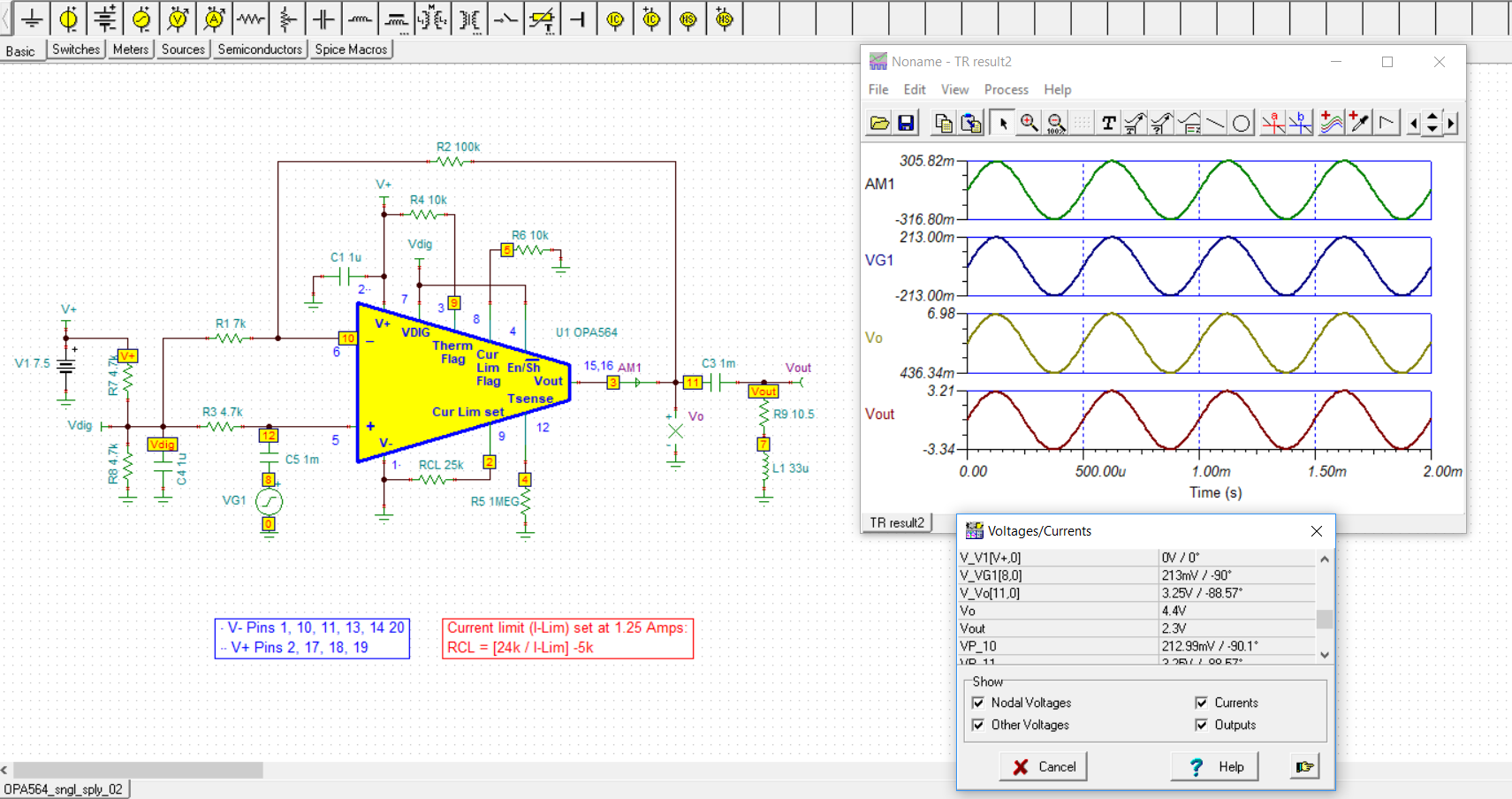
I have a simple audio circuit powering a 16 ohm inductive load with a current limit of 700mA using the OPA564  :

Open loop gain is only about 2.5 V. With feedback I can't go above roughly .8 Volts without getting significant distortion or drop out of the signal. I have put resistors in series with the load to account for possible current overdraw but the problem remains.

The input source is a quarter inch trs from a computer audio interface. 

Thanks for your time.

  • Kris
    The schematic difficult to read. Could you upload it again, and try black and white rather than color?

    Thanks
    Dennis
  • Sorry about that.

    Thanks,

    Kris

  • Need some more details to do an analysis to diagnose your problem.
    1) is the part heatsinked in any way? Power Pad soldered down to a PCB? How big is plane soldered to and what oz of CU on PCB plane? What is exact Impedance of load? L value? R Value? What is input signal range? Frequency? Voltage peak-peak?
    Please give details on resistor values and voltage levels of these pins on OPA561:
    ILIM (pin 4), E/S (pin 8), Flag (pin 9).
  • Hi Tim,

    The chip is uncovered and not heatsinked or soldered to a PCB. I am testing it with a breadboard with wires soldered to the pins. It is the DWD package with the powerpad on top. Unless I am mistaken, this configuration does not require a soldered powerpad. I have touched it periodically during minutes of use with a .45V input signal and it gets warm but not hot.

    The load impedance @ 1000hz is 10.5 Ohms and the inductance is around .33mH.

    The chip will handle frequencies from 20-20k hz. I have tried the chip with 6 double AA's as well as a 9v lithium rechargeable that claims 800mA continuous output.

    Using a 1000 hz sine wave input signal with .46V differential and close to 0mA current and dialing the feedback potentiometer such that the bottom resistor is 8000ohms and the top 2000ohms I get :

    output swing across load : .688V

    ILim / Iset :  1.033 Vdc with a 25k resistor added from pin to ground

    E/S : 3.51Vdc .456Vac   left unconnected

    IFlag : 1.7mVdc left unconnected

    If I reduce feedback such that output voltage swing is around .8V the overcurrent flag will raise well above .8Vdc and ac . Adding resistors to the output will not change this.

    Thanks and Regards,

    Kris

  • Please study the attached collateral.

    This should answer your questions.  

    In addition consider downloading the free SPICE simulator from TI, TINA-TI at:

    By building and simulating your circuit in TINA-TI many problems can be avoided before building it in the real world.

    OPA564 Analysis.pptx

  • Thanks Tim this helps a lot.

     I set up my circuit like this for now (Basically what you linked minus the buffer) . Feedback pot. is now also 100k :

     :


    However, actual output voltage is only 3 Vrms. Is this due to the lack of the Vdig/Vmid buffer?

  • Hi Kris,

    Tim is on vacation for a couple of weeks so I will assist you.

    Your TINA circuit schematic indicates that V1, which is the V+ supply for the OPA564 is set to +7.5 V, and the output current is approaching one-half ampere. The OPA564 output swing to the supply rails with that load current will be about 0.5 V, or the output can swing as a maximum will be limited to about +0.5 V to +7 V. Therefore, the maximum peak-to-peak output swing is about 6.5 Vpp.

    If we calculate the RMS voltage for a 6.5 Vpp sine wave, that is 0.3535 (Vpp) or 2.3 VRMS. Thus, unless the V+ supply voltage is increased to something greater than +7.5 V, the OPA564 cannot deliver any higher output voltage than 2.3 VRMS. It might swing a bit more if the input is increased beyond 213 mVpk (the maximum peak input based on a closed-loop gain of 15.3 V/V), but the output will be clipped because it has hit its maximum swing capabilities.

    I am not sure how your were able to attain the 4.52 VRMS, unless that is the RMS value of a severely clipped sine wave. I don't know what peak input voltage VG1 is set to, but knowing what that is would help in an analysis. When I simulate the circuit as shown below I find the output swing is limited to the 2.3 VRMS as calculated.

    I have attached my TINA circuit for your use.

    OPA564_sngl_sply_02.TSC

    Regards, Thomas

    Precision Amplifiers Applications Engineering

  • Hi Thomas,

    I understand my error now. I made the assumption that a voltmeter reads average peak to peak voltage and not average voltage (It is a cheap voltmeter so I think it is an average and not true RMS). Likewise, in my TINA circuit I assumed peak to peak on the input function generator voltage and so entered .45 V, hence the clipped 4.52 V output.

    My real circuit roughly goes to a reasonable 2.1 Vrms now without distortion. Everything makes more sense now. Thanks for the help and sorry for the confusion.

    Regards,

    Kris