This thread has been locked.

If you have a related question, please click the "Ask a related question" button in the top right corner. The newly created question will be automatically linked to this question.

TLV6001: Use it as a comparator

Part Number: TLV6001
Other Parts Discussed in Thread: TINA-TI, AMC1200

Hi everyone. This is Mike

I have some TLV6001 in my stock, and I, just in order to use them, Can I use them as a comparator?, I know there such devices as comparator which has a better fast response, but the time it takes to arrive here it's so long. 

The input frequency could be 1 to 70 Hz. I think is good, but I don't know If the Opamp could have some lagg or jitter because it is not designed as a comparator.

I saw this TI reference design tidu020a.pdf

  • Hi Mike,

    For such slow input frequencies, I wouldn't have any concerns. You'll just have to make sure that your design can tolerate the settling time that will come from the op-amp's slewing and settling behaviors. This device doesn't have back to back input diodes and can tolerate inputs up the full supply range, so as long as your input doesn't exceed the supplies you should be okay.

    You can use the same type of design principles to get hysteresis with an op-amp circuit as you can with a dedicated comparator. There shouldn't be any additional concerns as far as jitter.

    I would recommend using TINA-TI to simulate the behavior of this op-amp as a comparator, you'll be able to get very accurate results with our latest model and you can see how the device will perform in your circuit. The model can be found here: www.ti.com/.../toolssoftware

    Best,
    Paul
  • Hi Mike,

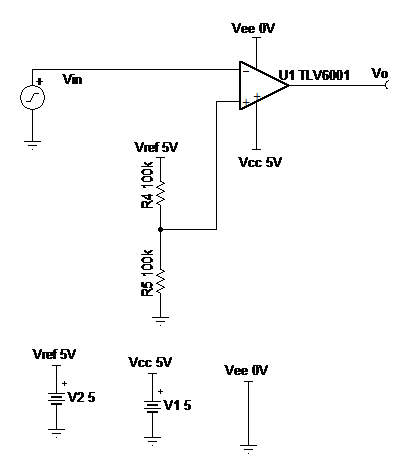
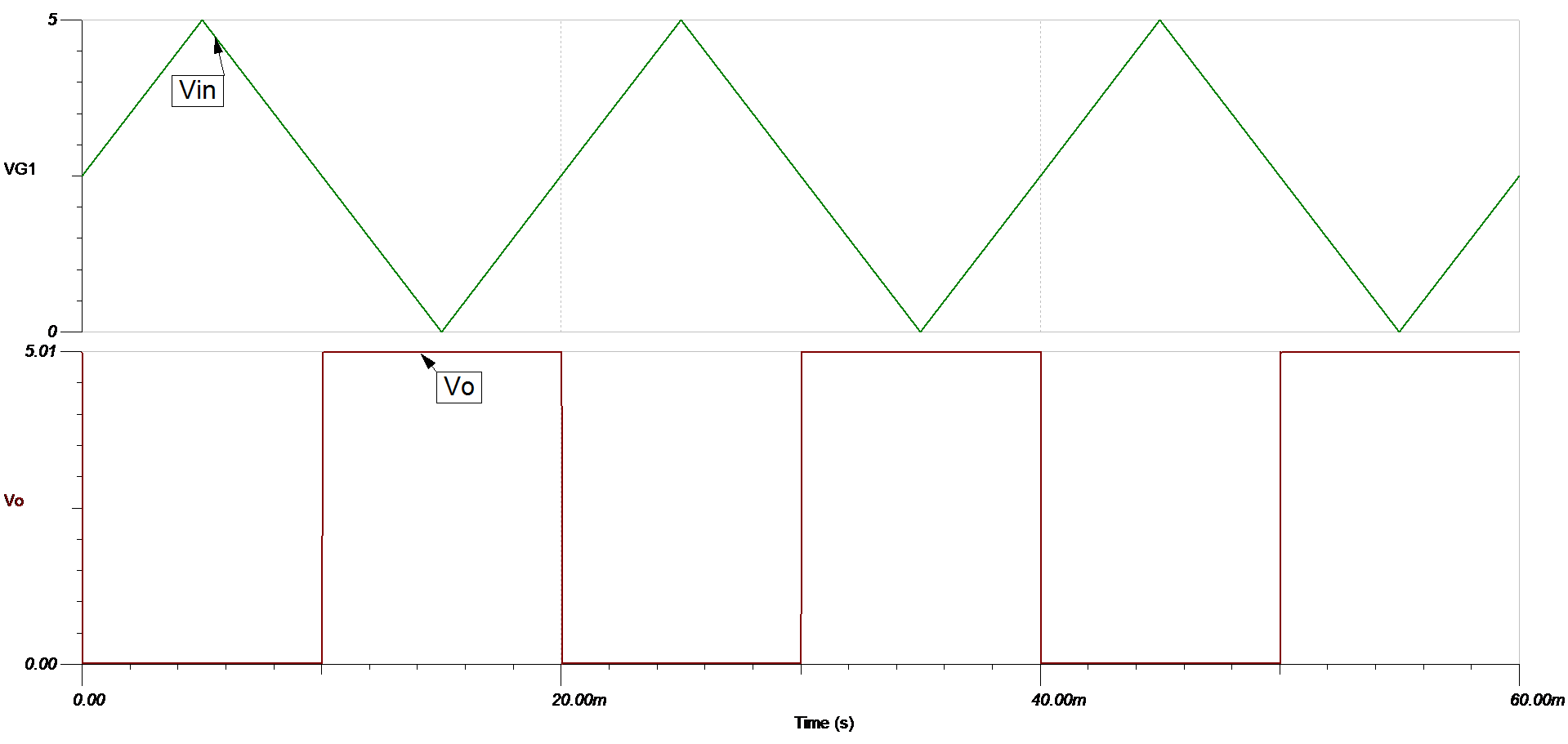
                    You can use TLV6001 as a comparator. Since your have a low frequency input, you shouldn't see much lag using TLV6001. But if you plan on using higher frequency input, I would recommend looking into other devices because you will be limited due to slew rate using TLV6001. For more information on comparator with and without hysteresis please visit:

    Comparator circuit using TLV6001

    Output and Input waveform

    I hope this helps!

    Best Regards,

    Bala Ravi

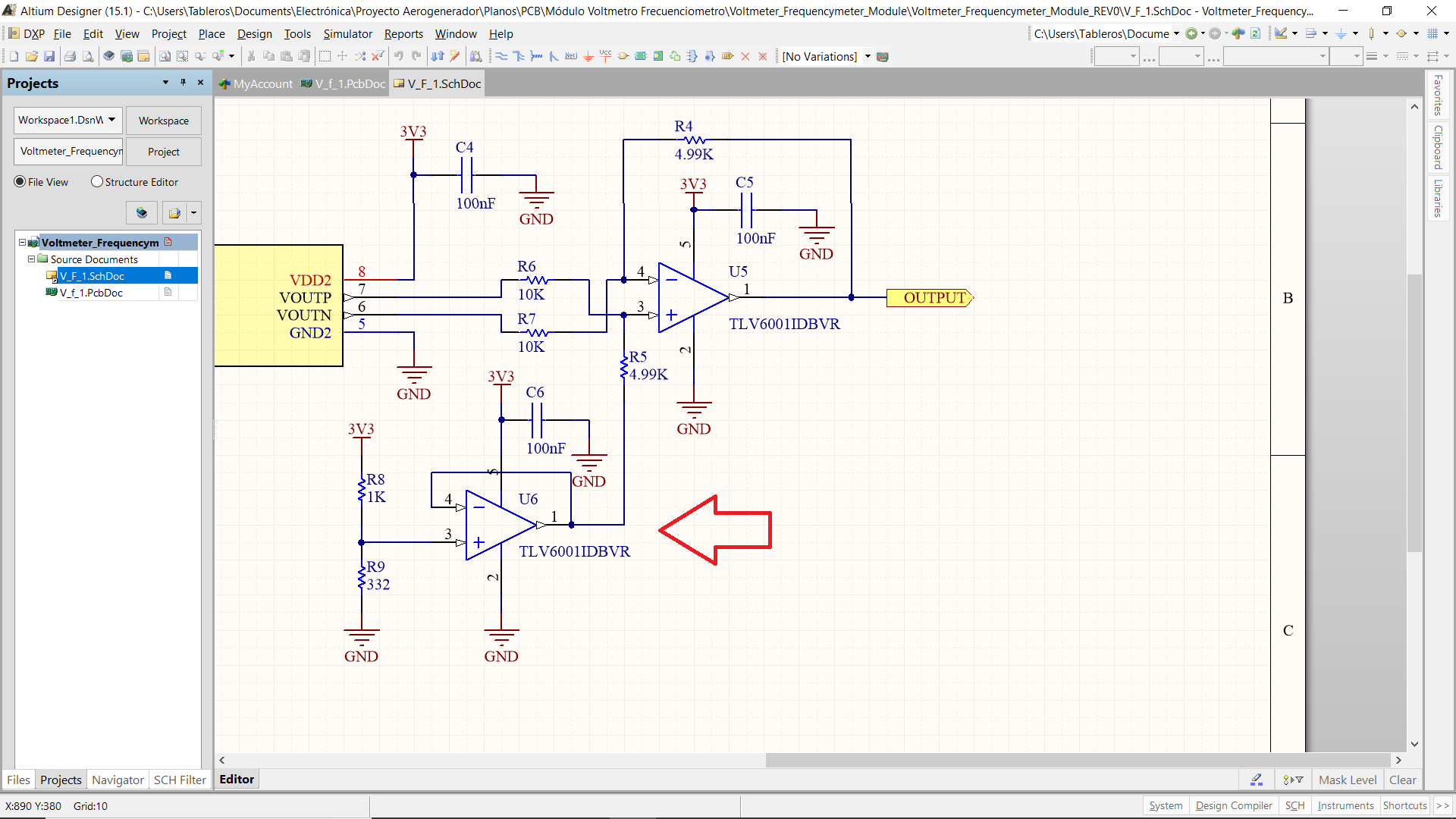
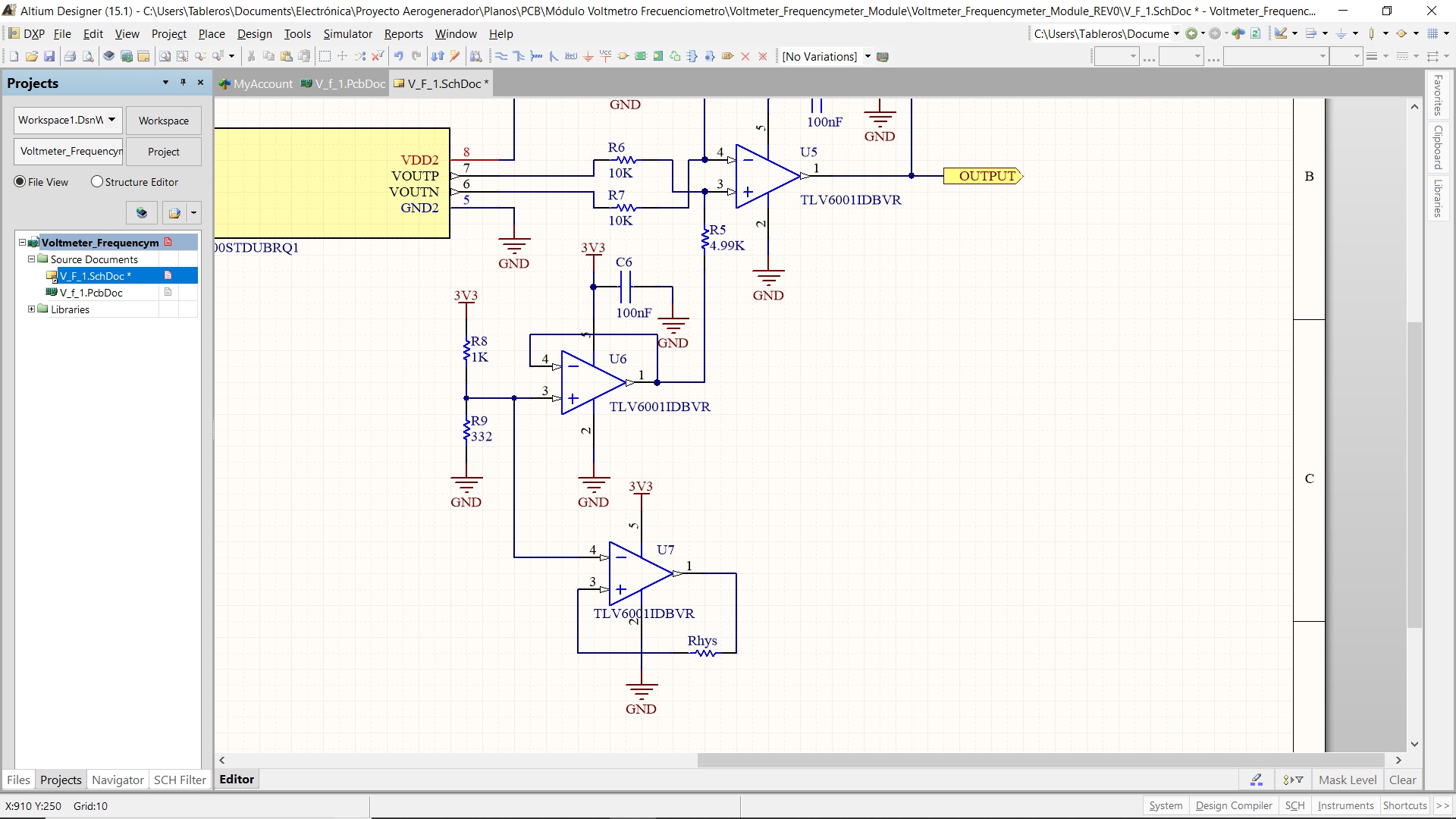
  •  Thanks both of you. This is the circuit I have. From the red arrow I want to take the Vref. Do you think is ok to take it from here? Will be some sort of problem of changing because of the 4K99 resistor

    Also I think I can use other op amp as a voltage follwer taken from here

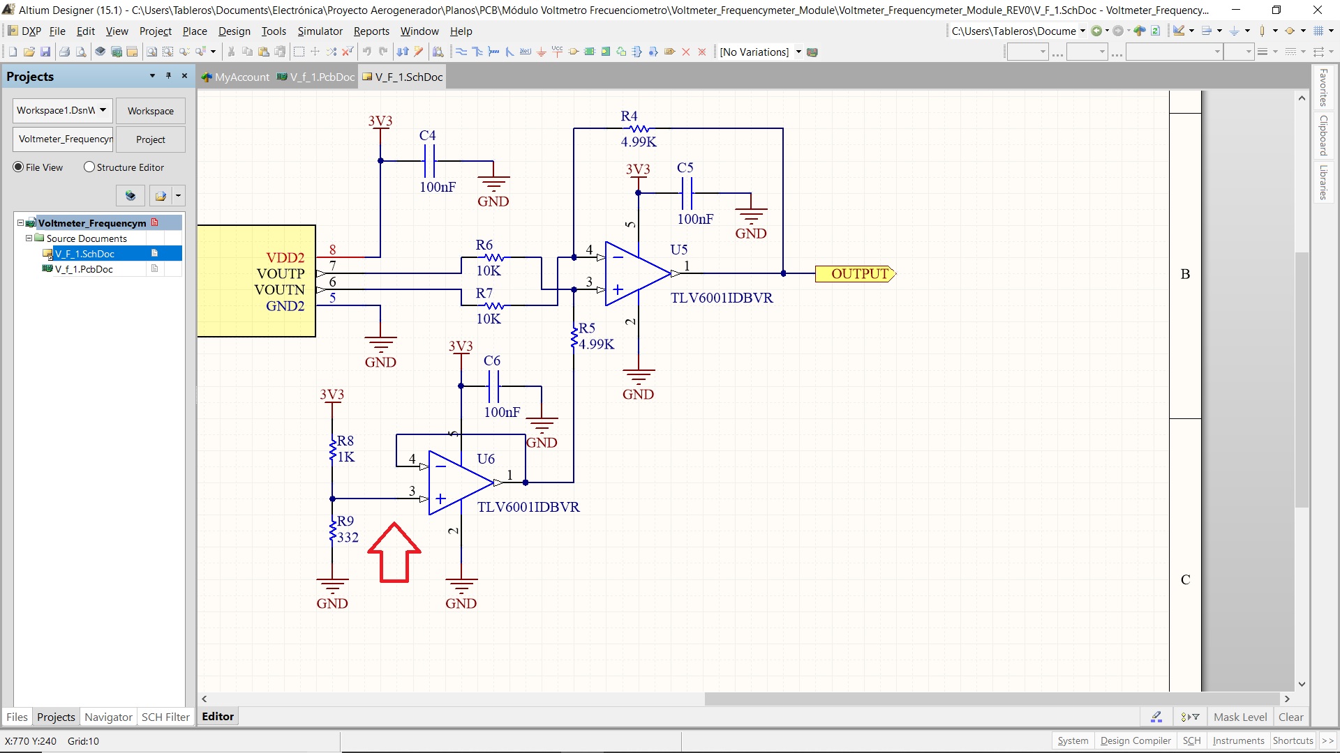
    Just like this?

  • Or do you recommend to use other Vref in order to do not scrapp the signal in the differential opamp?. I think making it , like the last image, it will change the Vcm and the signal will move .
  • Anybody out there?
  • Hi Mike,
    There is not much difference between setup 1 and setup 2. They both are buffer configurations. I would recommend setup 1 so that you can avoid some extra circuitry. I would suggest to watch out for the voltage drop across R5, to make sure your differential configuration is getting the correct Vref. You don't have to worry about exceeding Vcm level because this is a rail-rail in/out op amp, but be aware that changing common-mode voltage (Vcm) will affect your offset voltage (Vos). I hope this helps! Please let us know if you have any other questions.

    Best Regards,
    Bala Ravi
  • Hi Mike,

    yes, it's true, an OPAmp can sometimes be used as a comparator, if the demands on speed are not too high. But in any case I would introduce a hysteresis by feeding a small portion of the output signal back to the + input of OPAmp. This can usually be done by the help of a high ohmic resistor which is wired form the output to the +input while having some much lower ohmic resistance from the +input to ground, to a reference voltage or to the signal source itself.

    Whenever a comparator is used (a real one or an OPAmp used as comparator) switching noise can appear and it can be wise to buffer the involved signals, or at least to decouple it by the help of some capacitance.

    Can you show us a full schematic including the comparator circuit you plan to build? Then we can better find out how and where to buffer.

    Kai

  • kai klaas69

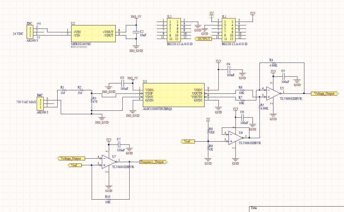
    Here it is

    The resistor of 10K was calculated from the theory in the app note I made reference.

  • Hi Mike,

    you could do it this way:

    Kai

  • Kai
    Thanks for the reply
    But I have some questions
    How do you determine the resistive divider? I mean, which one was the design criteria yo por those resistors? I think at the output it is going to be 600mV of offset to the differential amp. Then which one was the design criteria to put, at the output, those 10K resistors?
    Regards
    Mike
  • Hi Mike,

    according to the datasheet the AMC1200 generates a signal at its differential outputs VOUTN and VOUTP with an amplitude of 1V and an offset of 1.29V each. In the "scope" plot of simulation these two signals are represented by the olive green and blue curves. To convert this differential signal into a single-ended signal (green curve) the difference amplifier U1 is used. U2 is pushing up the output signal of U1 by 1.8V.

    The output signals of U1 and U2 are not directly connected to the inputs of comparator U3 but via R7 and R8. This is done to suppress unwanted feedbacks from the switchings of U3 into the outputs of U1 and U2. There's always enough parasitic capacitances which allows switching noise from the output togglings of U3 to run back into the outputs of U1 and U2. R7 and R8 imit the associated currents and allow U1 and U2 to suppress the switching noise in combination with their non-ideal open loop gains and open loop output impedances.

    R8 in combination with R9 additionally forms a hysteresis for comparator U3: When the output of U3 is low the hysteresis is 1.8V / 1010k * 10k = 18mV. When the output U3 is high then the hysteresis is (3.3V - 1.5V) / 1010k * 10k = 15mV. This is enough for this kind of application.

    The values of R7 and R8 are based on experience. There's no special rule for choosing them. You can decrease R7 and R8, if you see that the outputs of U1 and U2 are clean enough.

    Kai
  • Kai
    I want to apologize my self I saw R5 1K as R 5.1K, That´s what I said something about 600mV. Can I move the offset? , I mean, Can I decrease the resistor divider in order to get 1.29 V instead 1.8? Or you recommend to leave it as yours, I say this because my differential signal will increase, with 1.8Vref, up to 3.3V which will damage the ADC input (this circuit will feed the ADC input of F28069M Launchpad)
  • Hi Mike,

    yes, you can move the offset.

    Kai
  • Kai
    Just One question more
    How do you put some loead in the opamp, as you said, is beacuse of your experience, but there are some guidelines like "If the output is high enough and the load is XX Kohms is ok" or something like this
    Thanks
    Mike
  • Hi Mike,

    a usual OPAmp can handle output currents in the range of 100µA...1mA. In combination with the usual supply voltages this results in load and feedback resistances in the 10k range.

    Kai
  • Thanks for all Kai!

    Regards
    Mike
  • It's a pleasure. Good luck!

    Kai