This thread has been locked.

If you have a related question, please click the "Ask a related question" button in the top right corner. The newly created question will be automatically linked to this question.

OPA2277: Set point noise at the ends of the Pot.

Part Number: OPA2277
Other Parts Discussed in Thread: TINA-TI

I am using OPA2277s to produce a precision setpoint with an external adjustment. The output noise is okay until either end of the potentiometer is reached and then the noise level jumps up almost .25 volts. Any ideas why?

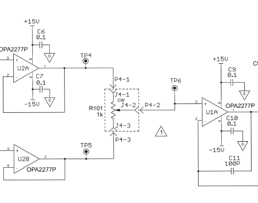
We can mitigate the noise by placing a resistor between the wiper of the potentiometer and the second opa2277. 

  • Hi Joe,

    I assume the output noise is being observed at the output of U1A. Have you measured the voltage at the U1A non-inverting input when the potentiometer is adjusted to its extremes? Do keep in mind that the OPA2277P VCM, Common-mode voltage range (V–) + 2 to (V+) – 2 V. If the voltage exceeds +/-13 V at the non-inverting input the VCM range would be exceeded and all electrical performances, including noise would be much degraded. Do note that the OPA2277P output swing range of U2A, U2B could be at a level that exceeds U1A VCM range.

    Not certain, but adding the series resistor could be limiting the input current and lessening the effect.

    Regards, Thomas
    Precision Amplifiers Applications Engineering
  • Thomas,

    Thanks for the info. I will check those voltages. A little more info for you, essentially what I am doing is setting the span of adjustment with U2. U2A is setting the high limit and U2B is setting the low limit. These are generally set to 0-5V of 1-5V. I tried an experiment where I put a 20 ohm resistor between the wiper of the pot and U1. This almost completely eliminated the noise on the high end (U2A), but the reduction on the low end was still not adequate. This seems odd to me as U2 is powered by +/-15V being at/near 0 shouldn't be a problem. I also tried it 1-5V and the low side was still noisy.

  • Hi Joe,

    when the wiper reaches the end of resistance element, contact problems can occur. The resistance between wiper and resistance element can heavily increase due to oxid layers. The oxid layer often forms a parasitic semiconductor which can zener like a zener diode. This can result in heavily increased noise. Even an instability of OPAmp can occur, because this parasitic zenering effect can oscillate by itself. You can observe this generation of excessive noise, especially if the trimmer is old, oxidized or sulphated. The insertion of a current limiting resistor can help, either at the output of driving OPAmp or between the wiper and the receiving OPAmp.

    Another issue is noise injection. Such a trimmer is usually unshielded and when you touch it with a screw driver you can directly inject HF interference into the circuit. This can destabilize the trimming circuit and cause oscillation.

    Instability due to unwished load capacitance is another issue which can mostly be observed, when the wiper reaches the end of resistance element, because then there's no isolation resistance between the output of driving OPAmp and the trimmer terminal which looks capacitive. The insertion of a 22...100R isolation resistance can help then.

    Capacitive feedback is another issue which can make trouble with trimming circuits. This can often be seen when the ground routing and/or the supply voltage decoupling of OPAmp is improper. In such cases there's usually a stray capacitance from the output of U1A back to the trimmer terminals or even the input pins of U2A. A simple resistor between the wiper and the receiving OPAmp forming a low pass filter in combination with the input capacitance of receiving OPAmp can help. A solid ground plane and proper supply voltage decoupling is the best cure against capacitive feedback, though.

    In my circuits I have always an isolation resistor between the output of driving OPAmp and the according trimmer terminal. And I have always a passive low pass filter between the wiper and the receiving OPAmp. In big circuits it's extremely helpful to have passive input low pass filtering at each OPAmp. And, analog circuits do also heavily profit from a solid ground plane...

    Kai

  • Hi Joe,

    Have you checked the noise at the U2A (TP4) and U2B(TP5) with R101 near center? I am wondering if the noise level is present at their outputs all along, and adjusting the potentiometer to one of the endpoints simply results in the noise level being fully applied to the U1A input (TP6).

    Is this a new OPA2277P application, or has the circuit assembly been in use for some time? You mention the noise; do you have any information describing it in terms of the frequency range, amplitude, etc.? Do you have any images of the noise with the potentiometer at center setting and at the extreme endpoints?

    If this particular circuit assembly has been in use for some time Kai's discussion of potentiometer-related anomalies provides possible causes for the noise. Although I don't have direct experience with the product I see mentions on the on-line audio forums about a product intended for cleaning potentiometers called DeoxIT® FaderLube. It is as a moving contact lubricant.

    Regards, Thomas
    Precision Amplifiers Applications Engineering
  • Hi Thomas,

    This is not a totally new application of the OPA2277. The output structure, which I will post below, is at least close to things we have done in the past. Using it to set the span, U2, is new at least in this configuration. U2A is setting high point of the span, approximately 5Vdc. U2B sets the low point of the span, 0 to 1Vdc.  I checked the output of U1A and it adjusts from 3-8 Vdc, as it should. We are not getting anywhere near the +/- 13 Vdc rails. We are running the circuit with a 250 ohm load connected between C and D.

    I am also adding some o'scope captures. The dark blue trace is at TP6. The light blue is at the output of U1A. The green is at the drain of Q1. And the pink is at TP7. This is with a 20 ohm resistor added between the wiper of the pot and U1A-3. As you can see, the input, TP6, remains clean throughout the adjustment range. The other signals start showing noise around the mid point of adjustment and get worse as we get to zero.

    Thanks for the help.

    Hmmm...it doesn't seem to want to let me insert more files.

    set800 scope captures.pdfI guess it doesn't like pdf's.  

  • I guess it likes pdf's after you make the post.
  • Hi Joe,

    this isn't noise. This is oscillation! Does is come from the 250R load? Where is it connected to?

    Looks like the U1A circuit is unstable.

    Kai

  • Hi Kai,

    The load is just a 250 ohm resistor attached between C and D of the connector. Sounds like we are heading down the same path. I am looking at the C11 (100pF) and R7 (165 ohms) filter. That is way fast for what we are doing here.

    Thanks.
  • Hi Joe,

    as a blind guess I would assume that increasing R7 could help. But why not running a phase stability analysis with TINA-TI? You might find these training videos useful:

    training.ti.com/ti-precision-labs-op-amps-stability-3

    training.ti.com/ti-precision-labs-op-amps-stability-6

    Kai
  • Thanks Kai,

    I will check out the videos, IT constraints not withstanding. 

    Increasing R7 (100k) corrected the issue.

  • Hi Joe,

    I have done some analysis on your circuit and can confirm that it is unstable:

    I would recommend the following changes:

    joe2.TSC

    joe3.TSC

    Kai