This thread has been locked.

If you have a related question, please click the "Ask a related question" button in the top right corner. The newly created question will be automatically linked to this question.

TLV9001: TLV9001 work as subtractor

Part Number: TLV9001

Team,

Now I am promoting TLV9001 to a headphone customer and expects the project to have high volume. TLV9001 is used to amplify the output singal of mic. The mic signal is differential and amplititue is around 10mVrms. Signal frequency range is around 20~10kHz. 

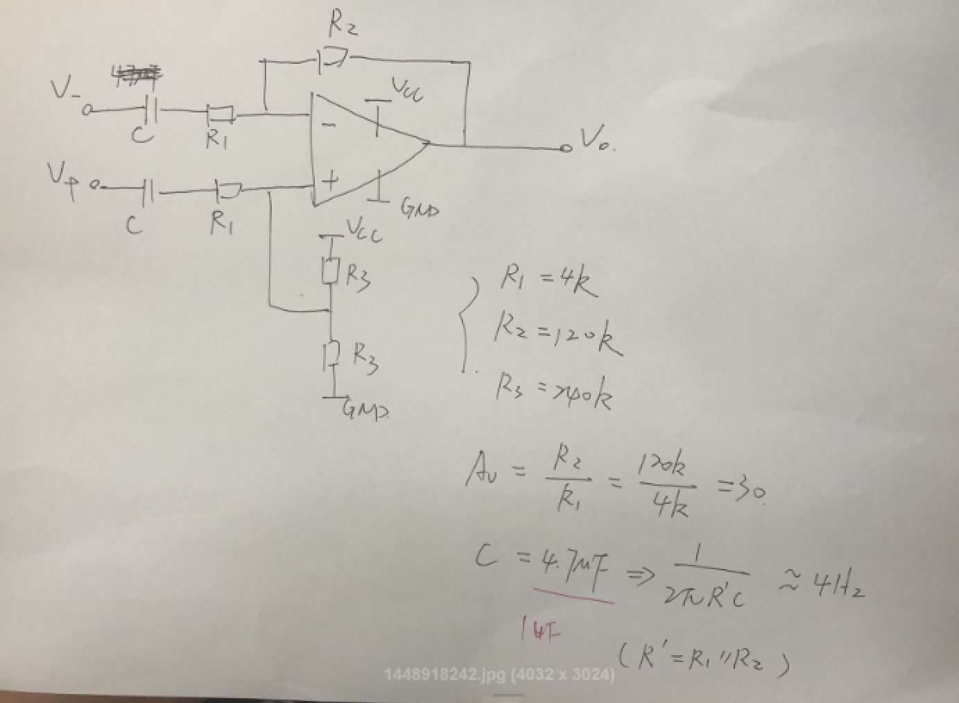
Below is the circuit that I am thinking of now. Gain is 30. Do you have any concern of it? Or do you have better option? 

Current AC couple capacitor is 4.7uF. Customer would like it to reduce to 1uF. Could I increase the resistance by 5 times to achieve that?

  • Please let me konw as well if I am wrong in the calculation. Thanks!
  • Hi Nic,

    The main concern I have is that the customer is using a voltage divider (R3) to bias up the output. We typically recommend supplying a reference voltage with a low impedance node such as a buffered voltage divider. This TI Design shows an example of this. Not using a low impedance node will degrade the CMRR of the circuit due to the mismatch in resistor values.

    I also recommend taking a look at the "Difference amplifier (subtractor) circuit".

    We also have "TIA microphone amplifier circuit" and "Non-inverting microphone pre-amplifier circuit" that your customer may be interested in.

    Thank you,

    Tim Claycomb

  • Hi Nic,

    One thing I noticed is that R3 is set to be 2 times greater than R2 so ideally the equivalent resistance of the resistor divider to set the bia voltage will equal R2. So the performance of this circuit may be acceptable to the customer. 

    I also forgot to comment about your calculations. The cut off frequency due to C and resistors is equal to 1/(2*pi*R1*C). I have put your circuit into TINA and attached it to this reply so your customer can simulate their circuit and see if it meets their requirements.

    If they would like to add some high pass filtering as well they can add a capacitor in parallel to R2 and capacitors in parallel to both R3 resistors that are 1/2 the value of the capacitor in parallel to R2. The cut off frequency of the high pass filter (if feedback caps are used) is equal to 1/(2*pi*R2*Cf).

    Thank you,

    Tim Claycomb

    TLV9001_Mic amp.TSC

  • Hey guys,

    Might you not be able to reduce the blocking cap value going into the non-inverting side as it is looking into 124kohm load? Might help cost or size
  • Hi Tim,

    Thanks for the detailed feedback! I believe what you are talking below is LPF instead of HPF, correct?

    "If they would like to add some high pass filtering as well they can add a capacitor in parallel to R2 and capacitors in parallel to both R3 resistors that are 1/2 the value of the capacitor in parallel to R2. The cut off frequency of the high pass filter (if feedback caps are used) is equal to 1/(2*pi*R2*Cf)."

    Nic

  • Sorry Michael, could you give more details? Why it is 124kohm? I think what Tim mention is 4kohm, right?
  • Can I set R1=20k, R2=600k, R3=1.2M, C=1uF to get cut off frequency =8Hz? 1/(2*pi*R1*C)=8Hz. Any concern of these values?
  • Hi Nic,

    Yes I meant to say LPF. Sorry about that.

    I think what Michael is referring to is the impedance looking from V+ you see 124kohms but if you look from V- you see 4kohms.

    There may be an issue with using high value resistors such as 20k and 600k. The issue is that the high value resistors can create too much delay in the feedback and cause stability issues. I recommend simulating the phase margin of your design to make sure you have 45 degrees of phase margin. If you have less than 45 degrees of phase margin you will need to add a capacitor in the feedback and in parallel to R3 to stabilize the amplifier. I recommend watching our TI Precision Lab videos on Stability for more information.

    Thank you,

    Tim Claycomb

  • Hi  Tim,

    I have different opinion of the impedance looking from V+ and V-. The small signal equivalent circuit should look as below. I think the impedance look from V+ or V- is 120k. They are the same. That is why I choose R3 to be 1/2 R2.

  • Interesting perspective. 

    When you close the loop for an op amp, the V- node is a virtual ground where the input impedance on that side sees only the Rg resistor as a load

    On the non-inverting side, the V+ input is high impedance so the input impedance is the sum of the resistors

  • Hi Nic,

    Michael is correct.

    Thank you,

    Tim Claycomb

  • Thanks Michael. Currently 4.7uF only has 0402 package, which is too large for customer PCB board. They only can accept 1uF. So how can we modify the circuit to get good DC blocking performance (maybe cut-off frequency<10Hz) with 1uF AC couple capacitor? Looks like increasing resistance is not acceptable.

  • Well, interesting problem - the attached uses an AC coupled T network to stay with 1uF values and do what you want. Looks promising in sim, but does add 3 more passives. I did have to stay with 1uF on the Non-inverting side to get the differential response at lower F better. 

    TLV9001_Mic amp updated.TSC

  • The high value resistor adding delay is maybe not the best way to think about it - it really adds a feedback pole to the inverting input parasitic which is by the parallel combination of Rg||Rf. I looked at phase margin a bit, looks really good with this part. All of these resistors have some parasitic C across them - I use 0.2pF for surface mount.

    Talked about these issues in detail in this article,

    www.planetanalog.com/author.asp
  • Hi Michael and Nic,

    I recommend watching our first TI Precision Lab videos on Stability where we discuss how too much delay in the feedback causes stability issues. 

    Thank you,

    Tim Claycomb

  • And the bandwidth span is not perfectly where you want it, but some slight adjustments should get it there. The Amplifier is pretty close to being the high frequency cutoff with its 1MHz GBP and noise gain of 31. Probably just need to reduce that feedback 100pF to get back out to 20kHz F-3dB. The lower end is tougher with the constraints - but do you really need 10Hz in a microphone app - its around 16Hz right now.
  • Yes Tim, I looked at the slide deck and what is there is a good intuitive description of loop phase margin problems via added delay in the loop. That is another way of saying you have more poles around the loop. The examples were very good but this "delay" is the same thing as a pole. Which you can fix with a zero - hence the common idea of adding a feedback cap to "speed up" the feedback loop that has a pole due to higher driving point impedance into a inverting parasitic C causing "delay" - but actually a pole in the beta, or a zero in the Noise gain. The delay idea is a good pictorial way, but when you start writing equations you are using poles and zeros not a transmission delay term.
  • And just to be clear, there is a Laplace delay expression that I do use in some cases - not very often in feedback circuits where the poles and zeroes in the noise gain are more useful.

    That term is an e^(-sT) - that is not what the precision labs are talking about so (for me) calling this a delay is perplexing given there really is a "delay" term I have to use in some cases.

    But I certainly understand the precision labs is trying to simplify a first level discussion more with pictures than equations - that is fine, but a loop delay in that context is the same thing as a loop pole and the point I was making for the feedback resistor values is the driving point impedance is Rf||Rg for that pole - so, while Rf might be pretty large, if there is a lot of gain like here, the impedance to use for the loop pole is <Rg.