This thread has been locked.

If you have a related question, please click the "Ask a related question" button in the top right corner. The newly created question will be automatically linked to this question.

OPA2189: OPA2189 capacitive drive

Part Number: OPA2189
Other Parts Discussed in Thread: OPA189

Hi,

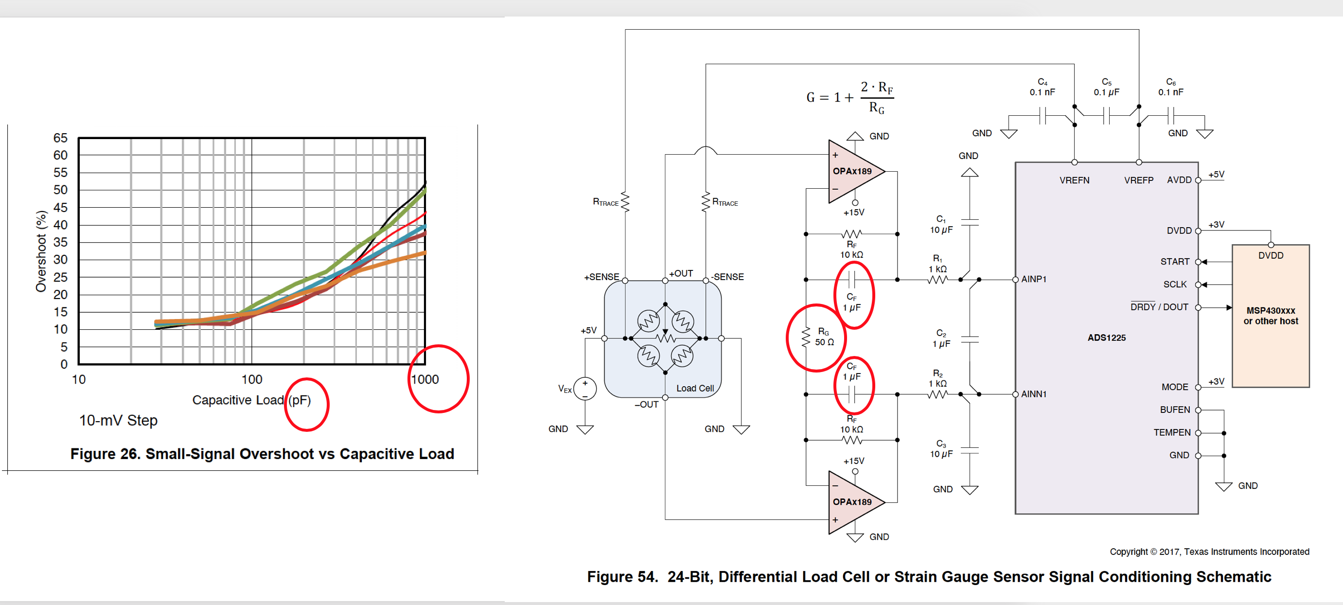
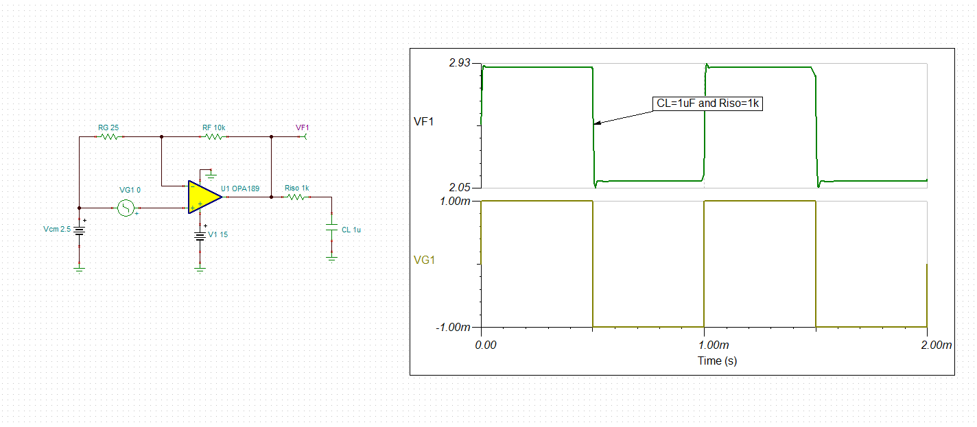
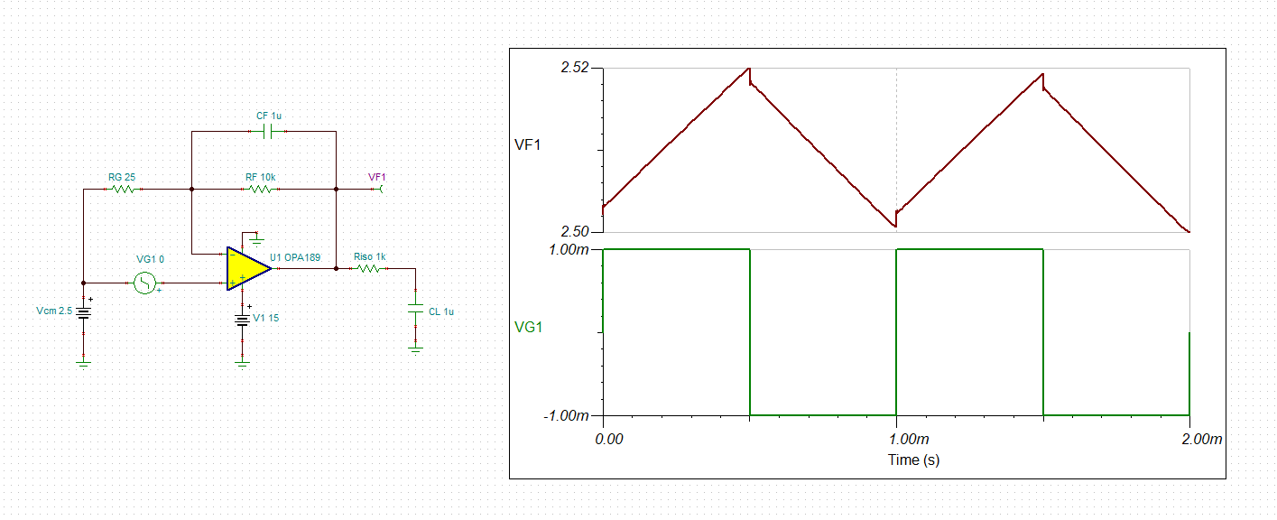
I'm trying to reconcile the OPA2189's capacitive drive (see typ op fig 26 which implies 1nF is close to the max capacitive load) with the differential gain applications figure (54) that shows a 1uF filtering cap being used with a differential gain configuration utilizing a 50-Ohm gain resistor. I'm pretty sure that this feedback resistor helps to isolates the amplifier from the capacitive load, is that right? Also, is there a way to understand the relationship between this resistance value vs. cap value and overshoot? Maybe a graph with curves for 0.1uF and 1uF cap values and different values of Rfb would be helpful.

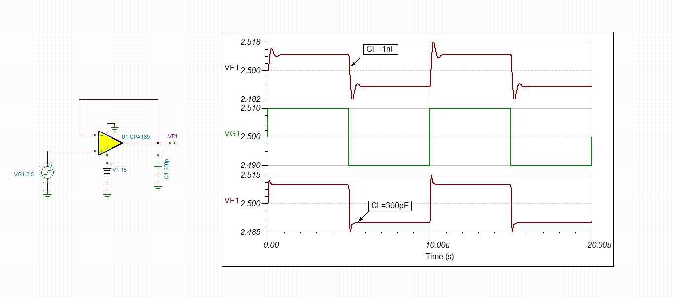
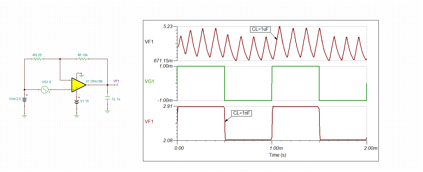
Or, does this simulate well using TI's simulation tools?

Thanks!

  • I mean gain resistor (sometimes referred to Rfb)

  • The rule of thumb allows maximum 25 percent small-signal overshoot (or minimum 45 degrees phase margin) to assure stability of the system over process variations.  Thus, according to Fig 26 above, which applies to OPA189 in a buffer configuration (G=1), you should not drive more than 300pF.

    Simulation below confirms that with CL=300pF, the small-signal overshoot is 25% (5mV/20mV) while for CL=1nF the overshoot is 40% (8mV/20mV).


    Increasing the close-loop gain, lowers the effective bandwidth of the circuit configuration and thus improves the capacitive load drive.  The equivalent 1/2 of customer's circuit is shown below and it indicates that the close-loop gain is G=400, thus the circuit may drive higher capacitve loads but NOT in the range of 1uF.

    Even though in G=1 OPA189 was only marginally stable (40% overshoot) while driving 1nF load, now in the gain of 400 it is very stable with almost no overshoot.  However, it cannot drive capacitive load of 1uF - see below.

    In order to be able to drive very large cap loads like 1uF, you must add Riso resistor between the output and capacitive load, which isolates the output from seeing directly CL.  Doing so stabilizes the system as shown below.  It is the series output resistor and NOT feedback resistor that improves the capacitve load drive.

    Please review TI precision lab material under following link, which explains the details of stabilization of the system:

    https://training.ti.com/ti-precision-labs-op-amps-stability-1?context=1139747-1139745-14685-1138805-13848

    There is no reason from stability point of view for adding 1uF capacitor across the feedback resistor, RF, (the system is stable without it) unless you want to filter out integrated noise or limit the system bandwidth to f = 1/(2*Pi*10,000*1e-6) = ~16Hz - see below.

  • Hi Marek, Thank you so much for your detailed response. This is quite clear. -Doug