This thread has been locked.

If you have a related question, please click the "Ask a related question" button in the top right corner. The newly created question will be automatically linked to this question.

INA826: Op Amp not clipping properly

Part Number: INA826

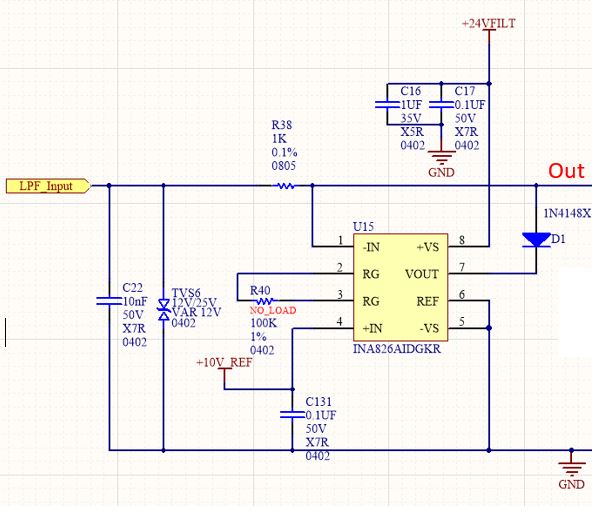
Issue: the circuit below uses x2 INA826AIDGKR.  It should follow any +/- input DC voltage to between 0-10Vs, and clip any voltage outside that range. Anything above 10V should be locked at 10V and anything below 0V should be locked at 0.

 Instead, we are seeing the upper clipping occur at 5.47V.
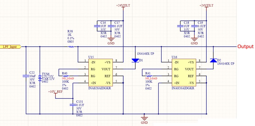
Notes:

R40 and R41 are NOT populated

Pin 4 has our 10V reference voltage.

 The first part of the circuit is supposed to track (follow) any input voltage below 10V, and clip any voltage above 10V. Instead, this section clips correctly tacks any voltage below 5.47V, then incorrectly clips higher voltages at 5.47V.  We have not taken any test data on the negative clipping section yet.

  • Hi Scott,

    For a single supply rail in INA826, the minimum V- rail needs to be 3V. You had in Ground. 

    For LPF input, you need to bias the voltage up above V-, since the Operating Input Vcm range is from V- to (V+)-1 Volts. I had bias the input signal at 10Vdc in simulation. 

    Please find the duplicated simulation you enclosed in Tina. I placed 5MOhm as the Gain Resistor, which it has too much thermal noises, but this is just for simulation purposes, rather leave it open. If you have other issues, please let me know. 

    INA826 02182020.TSC

    Best,

    Raymond

  • There are multiple points in the datasheet and EVM schematic that show -Vs can be connected to GND, so long as the difference between +Vs and -Vs is greater than 3V and less than 36V for a single supply. We thought design currently satisfies this. 

    When running your TINA simulation, the output is still clipped at 5.47V. Our LPF input can range anywhere from -5V to 20V. Our circuit must clip this input above 10V and below 0 volts. In your simulation, we tried changing the 3V at V- (Pin5) back to GND. Then we doubled the 10V across +IN (Pin 4) to 20V. The simulation now shows the voltage to be clipping properly at 0 and 10V. Why would this be the case if our RG is set to a gain of 1? Our TINA is uploaded below. 

    /cfs-file/__key/communityserver-discussions-components-files/14/INA826-02182020b.TSC

    Currently, we cannot bias V- (Pin5) up to 3 volts because this would clip our data at 3V instead of 0V as intended. If we truly need a 3V bias at V-, is there a drop-in replacement part that will cause our circuit to function as it stands today? 

  • Hi Scott,

    Please let me if I understood what you want to do in the inquiry. 

    1. LPF Input voltage can be ranged from -5V to 20V, triangular wave with signal amplitude at 12.5Vpp. 

    2. You only have 24V single voltage supply rail, and 10V reference voltage. You do not have negative voltage rail. For the 25V peak to peak input voltage swing, your single voltage rail is slightly low. We may have to reduce is with some kind of resistor divider. 

    3. There are two parts of circuits. 1st part op amp circuit is to track input voltage from -5V to 10V. (you could use a Op Amp buffer here)

    4. What does the second part of Op Amp circuit do?

    It does not seem that you need Instrumentation Op Amp for the design. Please let me know. 

    Best,

    Raymond