This thread has been locked.

If you have a related question, please click the "Ask a related question" button in the top right corner. The newly created question will be automatically linked to this question.

Voltage differential IC

Other Parts Discussed in Thread: LM2903B, LM358B, LM2904B

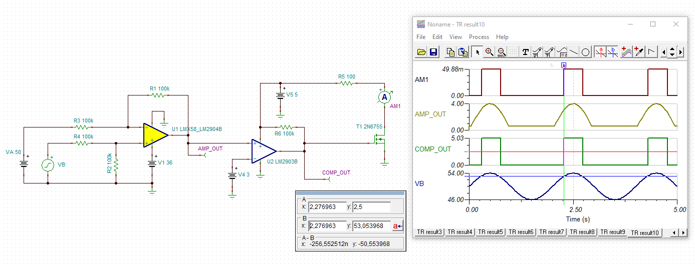
What is the most efficient solution to compare the voltages of two batteries ( voltage range of each battery: 40-62Volt)

and when there is a voltage difference greater than 3Volt between the two battery voltages-> get an output signal, capable of energizing a relay( 5-10Volts) .

Example: VoltageBatteryA = 50V and VoltageBatteryB = 54V OR VoltageBatteryA = 55V and VoltageBatteryB = 51V

  • Alexandros

    If I am understanding correctly, you want to know when the difference is greater than 3V (either positive or negative) and the battery ranges are 40 to 62V.

    Please confirm.

    Also, you mentioned energizing a relay.  Please specify how much current needs to be sourced? 

    Chuck

  • "If I am understanding correctly, you want to know when the difference is greater than 3V (either positive or negative) and the battery ranges are 40 to 62V." ->Yes.

    Also, I would like to energize a Solid State Relay, 5V - 50mA.

    Thank you

  • I’m imagining a circuit that utilizes 2 difference amplifiers and a dual comparator.

    The comparators would drive two NMOS transistors in parallel that would provide the ground connection to enable the relay if either voltage source is greater than the other by more than 3V.

    What voltage sources are available in the system? We may need to regulate one of the high voltage sources down to 30v so standard components can be used.

    If that sounds reasonable I’ll draw that up early next week.

    Chuck

  • We may scale down to 30V or even lower in order to use standard componetns. The availavle volatge sources are from +5V to +15V. We could use higher Voltage sources, if needed.

    "If that sounds reasonable I’ll draw that up early next week." ->  It sounds useful and I would really appreciate it.

  • See the attached TINA for the concept.  This is 1/2 of the circuit where I monitor for VB being 3V greater than VA.

    The other 1/2 would be exactly the same but the connection of VA and VB would be swapped.  This would monitor for VA being 3V greater than VB.

    The output of this would go into the other comparator in LM2903B which would drive another NMOS in parallel with T1.  If either goes high, the relay will get its ground and will turn on.

    The 36V for the LM358B would need to be derived from VA or VB which can range from 40 to 62V.  A simple zener diode could be used.

    The 3V reference for the comparator would just be a resistor divider from the 5V source that you said is available.

    Hope this works for you.

    Chuck

    LM2903B_LM358B_DiffIN.TSC

  • Thank you  . It seems prominsing! To summarize, in order to be sure that I understood. For the half system, first, we have a LM358B or LM2904B with 2 inputs (VA,VB). The supply voltage can be provided from VA or VB clamped to 36Volt with the use of a zener diode(or with a voltage divider tha makes the 62V to 36Volt and the llower voltages, eg 40Volt to 23.6V ?). The output of the Lm358B will be compared with 3 volt( We get it from our main supply of 5Volt through voltage divider)  and will drive a  NMOS.

    The same procedure will be impemented with VA, VB swapped, right?

    One last quetstion...Should I  reduce the  inputs VA and VB, through a voltage divider, to levels lower than 36Volt?

    Alexandros


  • Alexandros

    You are close.  The difference amplifier configuration actually divides the inputs down by a factor of 2 because the input resistors and the feedback resistors are equal in value.  So not need to divide them down further.

    The zener diode is needed to shunt one of the voltage sources (either VA or VB) down to 36V in order to be the power source for the LM358B or LM2904B.  The input pins of the amplifier will never see more than 1/2 of VA or VB because of the external resistors in the circuit.

    Chuck

  • Thank you ! I will try it I will let you know!

    Alexandros

  • Hi Alexandros,

    I like the solution Chuck proposed. I would like to add that low toleranced resistors should be used in the differential amplifier.

    This is the simulation with ideal resistors:

    The following simulation shows the worst case with +/-1% toleranced resistors:

    So I would take +/-0.1% toleranced resistors:

    Kai

  • Thanks Kai for the excellent support.  I will be closing this post for now to give Alexandros a chance to try this suggestion.

    Alexandros

    No need to respond now, but feel free to come back if you have any additional questions.

    Chuck

  • Thank you ! Just the time before I order the components!! 

    Thank you both!