This thread has been locked.

If you have a related question, please click the "Ask a related question" button in the top right corner. The newly created question will be automatically linked to this question.

OPA2189: Voltage follower offset too high

Part Number: OPA2189
Other Parts Discussed in Thread: THS4561, OPA2140, OPA2192, OPA2210

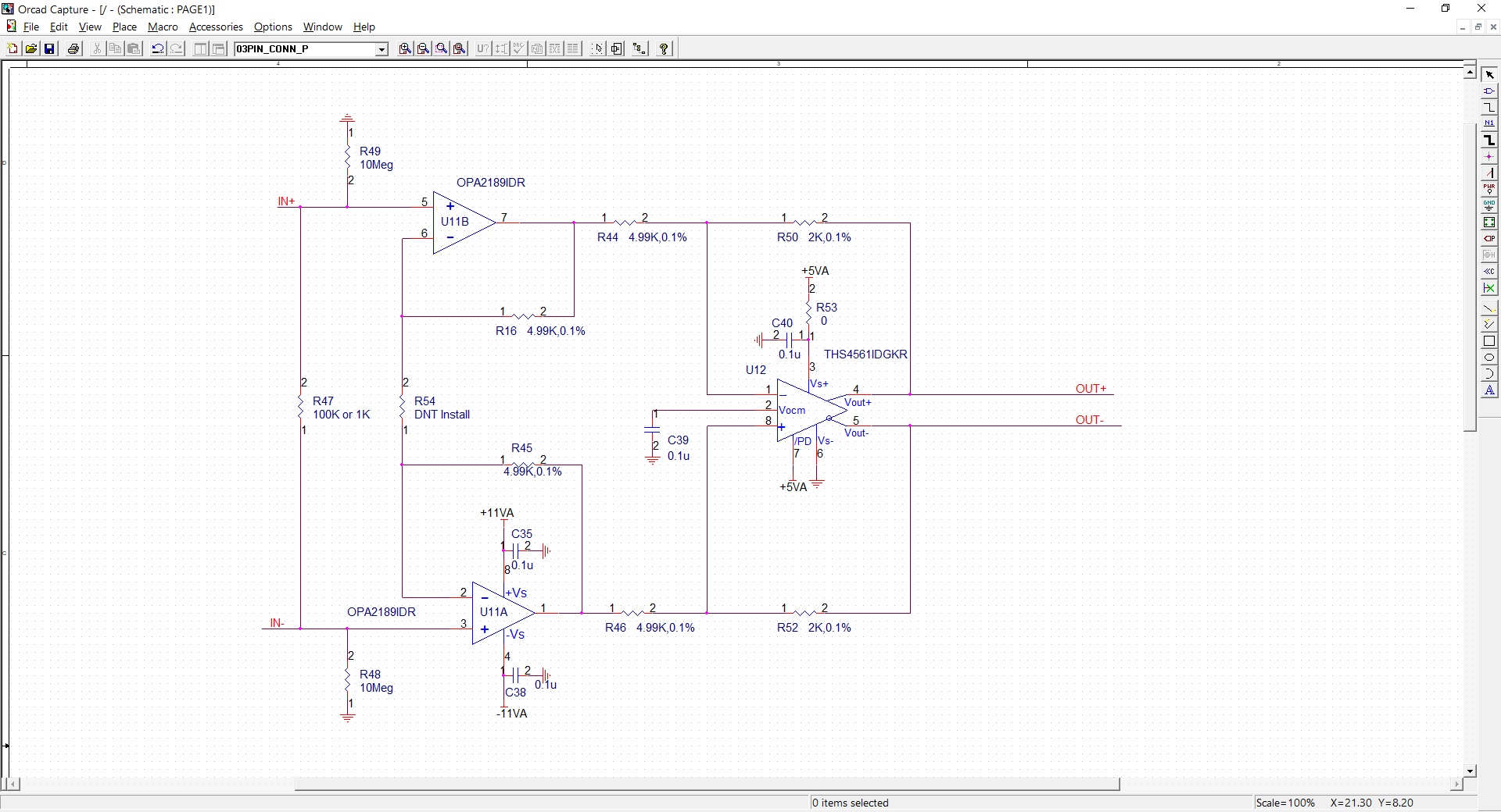
I am prototyping with OPA2189 because its very low 1/f noise. I use it for the input differential stage with 2 opamps and found there is big offset which is different from simulation. As in schematic, without any connection at IN+,and IN-, when R47 is 1KOhm, the OUT is < 1mV, but when R47 is increased to 100K Ohm, the DC OUT is about 3mV. The offset should not be this big. To figure out why,  I put only OPA2189 as simple voltage follower configuration, just as 1st stage (basically with R49 and R16, R48 and R45 with OPA2189), and Pin7 and Pin 1 output is around 20mV ~ 40mV, and their difference is 3mV ~ 20mV measured with multimeter . I did simulation with Pspice for TI, and the offset should be nearly 700uV (as shown in the Pspice for TI simuation) on one side, because the bias current is 70pA, 70pA * 10Meg = 700uV, why I get 20mV ~ 40mV (not very stable) instead 700uV. Thanks for the help.

  • Well you might be oscillating, try reducing the feedback R to 499 and when you probe with DVM, tack a 200 ohm leaded R on the output pins and probe on the other side of it to isolate the DVM input C> 

  • Hello John,

    Try Michael's suggested circuit changes and let us know what you find regarding the circuit's offset performances afterwards.

    What do you intend to connect to the IN+ and IN- circuit inputs? Are they low-impedance voltages sources, or some kind of sensor? The OPA2189 op amps use chopper technology to minimize the voltage offset. Although the op amp input bias current (Ib) is on average very low, the input chopping results in much higher peak input current levels. They are very short in duration, but the average Ib and peak Ib current has to come from somewhere in the circuit.

    The non-inverting inputs in your circuit see 10 MEG resistors to ground, and that presents an extremely high resistance return path for Ib. That could be affecting the offset you are are measuring. Even though there is a 100 kilohm, or 1 kilohm resistor between the IN+ and IN- inputs, one op amp input cannot supply the input Ib for the other. If the source resistance or impedance connected to IN+ and IN- inputs is low, then there shouldn't be a problem.

    I suggest reducing R48 and R49 to much lower value resistances and repeat you offset measurements. If the offset becomes much better, then that is a lead as to what is happening in the circuit.

    Regards, Thomas

    Precision Amplifiers Applications Engineering

  • Thanks for the suggestion. I changed the feedback resistor to 499 ohm from 4.99K, there is still big offset. I also checked the output with scope and there is no oscillator. 

  • This is for a geophysical instrument and IN+, IN- is connected to an electrode buried in ground. The electrode impedance ranges from several hundred Ohm to several kilo Ohm, and up to 100K Ohm in some extreme situation in desert, so the pull down R for bias current needs to be big.

    Currently the input instrumentation amplifier is AD8429 from ADI, but it has 1/f noise so I am trying to use OPA2189 to reduce 1/f noise. When I use 1KOhm resistor across IN+ and IN-, both AD8429 and OPA2189 are fine with low offset and output is stable. When I change to 100K Ohm, AD8429 still has low offset < 1mV and output is stable, but OPA2189 DC output is around 3mV, after continuous drifting for several minutes. But input bias/offset current of OPA2189 (70pA) is much smaller than AD8429 (~50nA) and should has less offset and more stable, both of them have 10Meg pull down.

    You mentioned that there is large bias current surge due to chopping, if I put cap ~270pF to pass the high frequency bias current to ground, will the opamp works with large bias resistor?  According to your suggestion, I reduce the bias resistor from 10Meg (offset ~20~40mV) to smaller value, OPA2189 offset becomes < 1mV when it is reduced to 100K Ohm. So with large R, OPA2189 is actually not in working condition, due to no small enough R to GND?  but why Pspice for TI software shows 0.7mV bias with 10Meg ? Maybe Pspice can not simulate this situation correctly?

    Do you have any suggestion or other parts to reduce 1/f? since 100K Ohm is too small in our application. Thanks.

    John Jiang

  • Hi John,

    Have you observed the OPA2189 U11A, U11B and THS4561 U12 outputs with a DSO when measuring the high and unstable offset voltage? I would like to know what you observe with a DSO at those circuit points. Just as you say the offset become much better with the 100 kilohm input resistors to ground, I suspect you will see one thing with the 10 MEG resistors, and something else with the 100 kilohm resistors in place. If you do see spikes or other noise it would be good for us to see the images.

    I have not tried adding capacitors off each of the OPA2189 non-inverting inputs to ground. That may help by reducing the impedance to ground and provide a current path for the transient input current. If you can try that please do share what you find. The capacitors should be close in value; chopper op amps perform best when the circuit is balanced. An X2Y capacitor would be a good choice try. They are inherently balanced by design.

    I suggest testing a non-chopper, very low-noise op amp in your circuit and see what level of noise performance you achieve. Some suggested precision op amps you may want to try in place of the OPA2189:

    OPA2140 - dual JFET input

    OPA2192 - dual CMOS input

    OPA2210 - dual super-beta bipolar input

    All have very low voltage offset, offset drift and relatively constant input bias currents (no chopping transients). Since their input bias current levels are very low the 10 MEG return resistors may not be a problem. Do realize that the 10 MEG resistors should be close in value to minimize bias current related contribution to the output referred voltage offset.

    Regards, Thomas

    Precision Amplifiers Applications Engineering

  • DSO has too much noise to see small signal like this. I check the signal with the next stage AD 24-bit in time and spectrum domain in Matlab after saving the data to SD card. I tried with some cap at the input and drifting issue does not improve. Your suggested non-chopping low noise opamp looks good and I ordered some and will do more tests with them later. Thanks.

    Regards,

    John


  • Hi John,

    It was worth a try adding the capacitors and it is good to know  for future reference that they didn't help. Do let us know how your application circuit performs with the non-chopper, precision op amps that I recommended.

    Can you close this e2e inquiry for now?

    Regards, Thomas

    Precision Amplifiers Applications Engineering

  • Thanks for your help.