This thread has been locked.

If you have a related question, please click the "Ask a related question" button in the top right corner. The newly created question will be automatically linked to this question.

TLV7041: Phone jack insertion detect

Part Number: TLV7041
Other Parts Discussed in Thread: LM317, OPA2210, OPA2140

Is there a recommended circuit to use for phone jack insertion detection? I have an SSR to trigger upon insertion.

This is a TRS jack with normals available for tip and ring. Shield is not referenced to ground, but the jack frame does have a chassis tie. Tip and ring are connected to the non-inverting inputs of two buffers via small series resistance -- 10Ω or so.

I can't send any significant voltage through any contact on the jack, as the source would see it briefly prior to any normal opening.

Source is either single ended or differential audio. Impedance could be anything from 100Ω to 1MΩ, so sensing that works, but of course it is ideal to have the insertion itself be the trigger.

I am assuming that the TLV7041 will supply voltage to a transistor that sends voltage to the SSR.

  • Jonah

    I am not specifically familiar with a circuit that has been promoted before.  However, in the past I recall seeing large pullup resistors being used on these pins.  When their is an insertion, the voltage drops below a threshold, say the midpoint of the supply because of the impedance to ground lowering the voltage on the node.

    You mentioned such a scheme would not work because the source would be adversely affected.  I am wondering if ac-coupling would somehow work.  Maybe connecting jack would create a momentary change in voltage and this could be latched with a large amount of hysteresis on the comparator.

    I just don't understand enough about the constraints of the system to be able to adequately provide a solution.  With impedance of 100 to 1M, that is also a challenge.  If you have any additional details to share, I can try to help further but at this point I am not sure what to offer.

    Chuck

  • Hi Jonah,

    as Chuck already mentioned, the usual way is to use a high ohmic voltage divider in order to minimize the impact on the signal. On the other hand, the switching current should not be too little because the switching contacts suffer from dirt and corrosion and need a certain minimum switching current for "free burning". In any case you shouldn't take the cheapest phone jack but a version with proper contacts.

    I would probably do it this way:

    Here 100k common mode input resistances are assumed for providing a current path for the input bias currents of differential amplifier.

    Kai

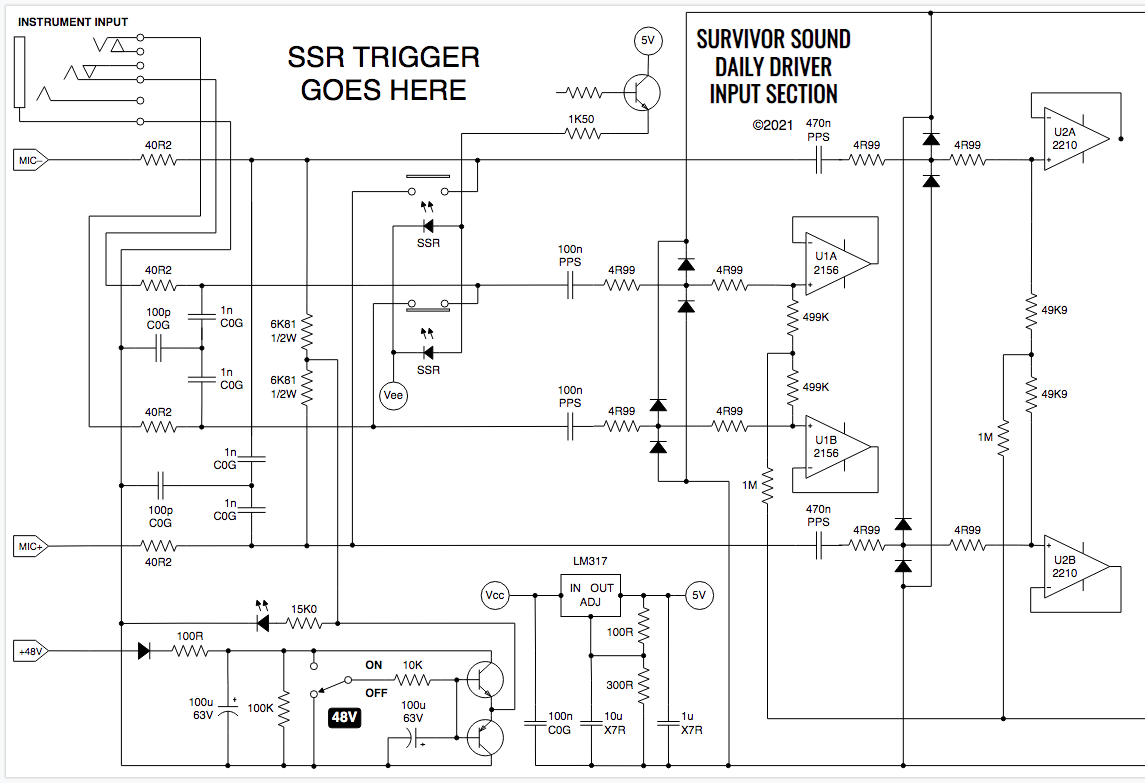
  • Hopefully this will clarify. The reason I say the source could be of basically any input impedance is because in any given pro audio situation, someone can plug any single ended audio source into an instrument input. And yes it is AC coupled with large value bias resistors to enable small value input capacitors. This system is built for either single or dual supply, by the way, with an internal midsupply reference generated by a voltage divider and buffer. U1A/B sums with U2A/B (not drawn here), so my method of input switching is to mute and unmute inputs. The goal is to do this without using a toggle switch. Jack is of appropriate quality, but I don't know if it's wise to send voltage back down the source line. Maybe low mV, but not ~860mV. I can't assume that any source will be AC coupled at its output, and sources such as electric guitars are DC coupled with a volume knob in series, so that would put DC on a pot, which is of course verboten.

  • Thanks for sharing the circuit but I am not sure that clarifies it much for me.  At the jack side of the 100nF capacitors, the node is floating when not connected.  So unless something was pulling it high initially, I cannot think of a way to know that something was plugged in.  Possibly you can detect on the non-Jack side of the capacitor with a window comparator and detect the presence of a signal that comes across the capacitor.  Sorry, that's all I can think of.  Maybe Kai will have a better idea.

    Chuck

  • Hi Jonah,

    I would probably do it this way:

    Kai

  • Kai

    Thanks for the suggestion here.

    Jonah

    When you have a chance to review, please let us know if this can work in your system.

    Chuck

  • Kai - thanks so much, this is mostly making sense for me. Chuck - getting there!  Let me know what you folks think of these variables and I will redraw this in a simpler fashion that might be useful for other people:

    I suppose with the 1n across the lines I could bring the RF caps down to a more normal 470p x 2 with 47p to chassis, or 1n x 2 with 100p to chassis with the low Rs I have in there.

    As a correction of my earlier DC talk, I realized that since the comparator is out of circuit from the view of the source once the plug is fully inserted, the DC concern would only be during insertion. I stopped trying to think of a scenario where 1V would be an issue, because it wouldn't.

    The one thing this doesn't do, however, is leave the 1M input impedance alone. Instrument inputs need something like a 1M load in order to replicate guitar amp input section behavior. Would removal of the 100K you have drawn in across the lines at the input require a simple adjustment of the comparator divider values, or does there definitely need to be a resistor there? If so, would I make it 2M and make the bias split resistors each 1M?

    If the answer to my last question is yes, I believe I'd have to raise the bias source resistor value as well to maintain the same common mode behavior. I suppose I could look at the 2156 and see what the maximum possible value would be without starting to induce additional CM voltage due to bias current (though I am probably switching to the 2140 in this architecture due to better noise specs below 100Hz). I think the 220n series caps could probably go back down to 100n with a higher differential termination.

    This is out of the specific scope of the comparator, but (Kai) do you think your surround-the-switching-point-with-caps approach would change if the transistor was triggering an actual mechanical relay, and if the contacts were disconnecting the source entirely and shorting the lines heading into the buffers? The SSR shunt approach is not really industry standard...it is a lot more common to see a DPDT 12V relay with supply from a 7812 or LM317, and the source gets cut off when the input is shorted. Just curious if the two 220n in series per line could be just one of half the value after the relay in that case, and if the 1n would be necessary.

  • Hi Jonah,

    I have acknowledged your post and will get back to you no later than the end of business Tuesday (2/16).

    I definitely have some catching up to do.

    Kind Regards,

    Joe

  • Hi Jonah,

    increase all my resistors by a factor of ten :-)

    Kai

  • Hi Jonah,

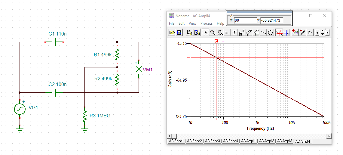
    there's another issue. I would imcrease the AC coupling caps. If they are too small, manufacturing tolerances can degrade the common mode rejection at low frequencies. In the following example a capacitance imbalance of 10% is assumed, which is not very much for metallized plastic foil caps:

    jonah_tlv7041_1.TSC

    Kai

  • Hi Kai,

    Thank you for your continued support.

    Jonah,

    Please let me know if Kai's feedback helped resolve your issue.

    Kind Regards,

    Joe

  • That's a valuable insight. Usually "increase the cap size" is problematic due to physical size if the input is bipolar, but because FET input / high Z / small cap, that could work.

    Vishay makes a sort of reasonably priced 3% THT polypropylene; I'll look for something 2%-5% in SMT PPS. Should cost less and help quite a bit.

    I'll redraw this and post it.

  • Hi Jonah,

    take care, the capacitance change due to soldering can be rather high:

    Kai

  • Kai –

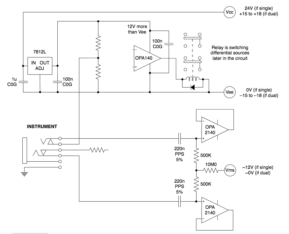
    I'll admit to being confused by your markups on my last drawing, partially due to scale and partially due to my own inexperience. Moving forward, this has switched to a mechanical 12V relay after the input section. The relay is switching what the following stage listens to: OPA2210 buffers on the mic input, or OPA2140 buffers on the instrument input.

    Here is a simplified version with a regular FET amp instead of a comparator package. Trying to go with something I know here as a starting point.

    I believe the divider would be 1M1 over 100K, that would give a 1V reference when a plug is inserted in the jack. But I'm missing something about what connects to what otherwise. I left everything open on the drawing below.

    Two sidenotes:

    1) Maybe it's better to run the V+ and V– of the divider and comparator to Vcc and Vee, respectively, and scrap the regulator? Trying to do this with the lowest part count. I'm a little leery of relying on Vcc and Vee for the divider and comparator because people can use this on single or dual supplies. The voltage wouldn't be predictable, but the ratio would be correct. I'd have to find a 24V relay that doesn't have any issue with 36V...most are fine with 30V. Alternatively, I could stick with a 12V relay and use Vcc and Vms for the comparator and divider, which at least would give me a reliable range from 12V to 18V that might be a little easier to accommodate. It's one relay so the typical concern about running a bunch of coils across half the supply shouldn't be a concern.

    2) If I'm calculating bias current correctly, common mode voltage after the OPA2140 should be something like -100dB to -80dB. That's 30dB lower than doing the same thing with 1/10 these values on an OPA2210 input. 

    Thanks

  • Jonah

    Unless there is a specific question regarding comparators, I’m going to need to ask that this be taken offline. Kai has offered some excellent design support but at this time I believe it would be best to continue this outside of the forum.

    Chuck

  • Hi Jonah,

    being my last answer before Chuck will close this thread.

    You could do it this way:

    Kai

  • That does clear some things up. Thanks for your time.

  • You are welcome and good luck :-)

    Kai