This thread has been locked.

If you have a related question, please click the "Ask a related question" button in the top right corner. The newly created question will be automatically linked to this question.

OPA192: Very low Current Sensing nA - uA

Part Number: OPA192
Other Parts Discussed in Thread: LOG114, STRIKE, TINA-TI

Hi,

I am working on the photodetector. And the photodetector has a resistance roughly ranging from 10^9 (dark) - to 10^6 (light) Ohm.

And I want to develop the circuit design which can measure the current signal with microcontroller unit (i.e., ATmega328 or ATmega328 based arduino board).

Therefore, the supplied voltage onto the photoresistor will be bounded to 5V (MCU's max Vdd = 5V).

In this case, is there any recommended circuit design to capture the current signal (nA - dark ~ uA - light) with low-noise.

I have tried  a combination of ADS1125 and AD623ANZ but failed to read the marginal analog signal variation.

I am a newbie to the "Electrical Circuit".

So please advise me if any of you have experience with the similar projects.

Thanks

Best

SJ

  • Hi SJ,

    Most of the circuits I see employing a photoresistor are used in simple applications where a light shining upon it results in an output circuit being switched. I suspect that is because they are relatively inexpensive and such simple applications do not require a high degree of accuracy and output linearity.

    Precision applications where an output voltage is highly proportional to an input current being generated from a varying light source most often employ a photodiode. The current generated by the photodiode is converted to an output voltage by an op amp. The output current from the photodiode is highly linear and predictable in high performance applications.

    The op amp is configured as a transimpedance (I-to-V converter). Transimpedance amplifiers using precision op amps are easily applied to handle input currents across several decades such as nA to uA and even more. The OPA192 has very high input impedance and very low input current amongst other attributes that makes it a good choice for a transimpedance amplifier. Certainly there are many other TI CMOS and JFET input op amps that are well suited for transimpedance applications. Here's an example of a TI Precision Design for a transimpedance amplifier and another from our cookbook:

    https://www.ti.com/lit/ug/tidu535/tidu535.pdf

    https://www.ti.com/lit/an/sboa268a/sboa268a.pdf

    On the more extreme end when an even wider range of input currents such as 100 pA to ~10 mA need to be accommodated, then a logarithmic amplifier such as the LOG114 is used. I don't think you need that much input current range so a op amp transimpedance amplifier should be fine.

    Regards, Thomas

    Precision Amplifiers Applications Engineering   

  • Hi SJ,

    what exactly do you mean by "photodetector"? A photoresistor or a photodiode?

    Kai

  • Hi Kai,

    I am using photodetector as a photoresistor.

    Thus, I tried to measure the analog signal (voltage drop) along the photodetector (which acts as a photoresistor)

    -- R1 --- Rphoto --- R2 ---

    With light condition, Rphoto decreases -> Vphoto decreases

    With dark condition, Rphoto increases -> Vphoto increases

    However, Rphoto is much higher than reference photodetectors R1,R2 (I used 10k). Therefore, I added OP-Amp. But this doesn't work.

    SJ

  • Hi Thomas,

    First of all, thank you so much for the detailed answer!

    Let me summarize your feedback.

    If I can apply the similar transimpedance amplifiers using OP-Amp such as OPA192, I can have a voltage output from the OP-AMP which is proportional to the input current. Is that correct?

    Then, I can just replace the photodiode in the circuit following https://www.ti.com/lit/ug/tidu535/tidu535.pdf with the photoresistor I am using.


    My question is

    1) If my application requires very low frequency (10~60 Hz), is this method still applicable?

    2) Does the MCU I am using affect the performance as well? If so, do you have any suggestions on it?

    Best,

    SJ

  • Hi SJ,

    No, a photoresistor and a photodiode are really quite different in the way they work and what they do. When light shines on a photoresistor all that happens is it's electrical resistance changes as function of the light intensity. It does not generate an electrical current when the light photons bombard its surface. Quite different in its behavior a photodiode actually generates an electrical current when the photons strike it. That current is converted to a corresponding voltage with the transimpedance amplifier that I discussed.

    You could apply a voltage source to one lead of the photoresistor and connect the other lead to the input of the op amp transimpedance amplifier. However, unlike the photodiode that has very little current generated when the light is absent (dark current) the photoresistor exhibits some high resistance in the dark and current will flow when the voltage source is connected. When dark, the transimpedance amplifier will have almost no output voltage with the photodiode but produce some level of output voltage with the photoresistor present.

    Regarding your questions:

    1) If my application requires very low frequency (10~60 Hz), is this method still applicable?

    Ten to 60 Hz is very low frequency almost any circuit you apply should work in that frequency range without speed concerns.

    2) Does the MCU I am using affect the performance as well? If so, do you have any suggestions on it?

    The MCU will follow whatever circuit you employ to activate the photoresistor. It will likely provide the buffering that is needed between the photoresistor and MCU.

    Regards, Thomas

    Precision Amplifiers Applications Engineering

  • Hi Sj,

    your photoresistor is a bit too high ohmic. So, either you look for a more low ohmic photoresistor or you increase the resistor in the voltage divider. In the latter case you could proceed in the following way:

    For the picture and the TINA-TI simulation file, see here:

    https://e2e.ti.com/support/amplifiers/f/amplifiers-forum/993491/opa192-belongs-to-this-thread

    The lower 22M resistors is what you still get in an electronic store, usually. If not, put four or five 10M resistors in series.

    The 47pF cap forms an input low pass filter and helps to keep the OPAmp stable.

    The 1k resistor protects the input of OPAmp during experimenting by limiting the input current.

    If can buy a lower ohmic photoresistor, you can decrease the 44M resistor and increase the 47pF by the same amount. The 1k resistor should stay where it is. It also helps to limit the inrush current from this filter cap into the input of OPAmp. But this only becomes relevant, if you heavily increase the 47pF capacitance.

    The 1k resistor and the 100nF cap at the output of OPA192 form a charge kick-back filter for the ATMEGA328. I have worked with this µC a lot of times and this charge kick-back filter will do beautifully.

    Good luck Relaxed

    Kai 

  • Hi SJ,

    See Kai's circuit for a photoresistor amplifier using the OPA192 as a buffer amplifier:

    https://e2e.ti.com/support/amplifiers/f/amplifiers-forum/993491/opa192-belongs-to-this-thread

    Regards, Thomas

    Precision Amplifiers Applications Engineering

  • Hi Kai,

    I have ordered the components you suggested and now I am trying to make a customized PCB board for the above circuit.

    Regarding MCU, do you think it is okay to use the Arduino UNO which also uses ATMega328P?

    By the way, could you also suggest ADC that can work well with the suggested circuit?

    If you don't think it's necessary, please share your thoughts on that as well.

    I hope this will work so that I can make some progress!

    Thanks!

    Best regards

    SJ

  • Hi SJ,

    can you tell more about your application? Is it just a learn and fun project? Or do you want to measure light intensity very accurately? In the latter case I would recommend a photodiode, like the BPW34, as a photodiode is more precise and faster. And it provides a lower temperature drift.

    Having said this, the advantage of photoresistor is its slowness so that you will not have to do much low pass filtering and averaging to remove eventual 100Hz components.

    Kai

  • Just forgot: I think the ATMEGA328 with its 10bit ADC should do.

    Kai

  • Hi Kai,

    This project is related to the Photoresistor I fabricated by myself. I have analyzed the performance in the probe station setup. And now, I want to prove that this photoresistor is applicable for hand-held applications with PCB boards. That is why I cannot change the photoresistor or switch it to the photodiode. Accordingly, I need to make a circuit that can measure the light intensity very accurately from the fabricated photoresistor.  

    By the way, what do you mean by "slowness" 

    the advantage of photoresistor is its slowness so

    Thanks

    Best

    SJ

  • Hi SJ,

    photoresistors show a consirable response time or latency.

    See these links:

    http://lednique.com/opto-isolators-2/light-dependent-resistor-ldr/

    https://en.wikipedia.org/wiki/Photoresistor

    Kai

  • Hi Kai,

    Yes I have already reviewed this LDR.

    I have one additional question.

    How did you simulate the OPA and your circuit?

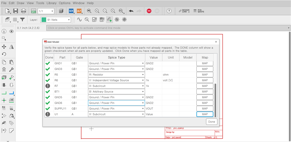
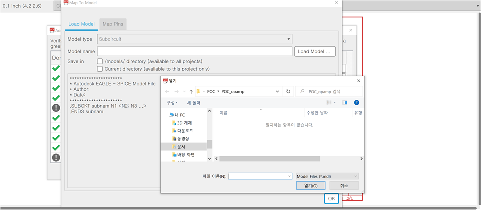
    I am currently using Autodesk Eagle S/W (this is non-changeable) and I am having trouble in mapping the OPA schematic to the spice model (Eagle requires .mdl extension). Do you know where I can find the .mdl extension model file for the OPA192?

    (Sorry for some Korean words)

    Thanks

    Best

    SJ

  • Hi SJ,

    I use TINA-TI:

    www.ti.com/.../TINA-TI

    Kai