This thread has been locked.

If you have a related question, please click the "Ask a related question" button in the top right corner. The newly created question will be automatically linked to this question.

OPA356: Amplification for Ultrasonic NDT Signal

Part Number: OPA356
Other Parts Discussed in Thread: LMP7718, THS4551, OPA838, OPA365, LMH6703, OPA859, OPA858

Hello,

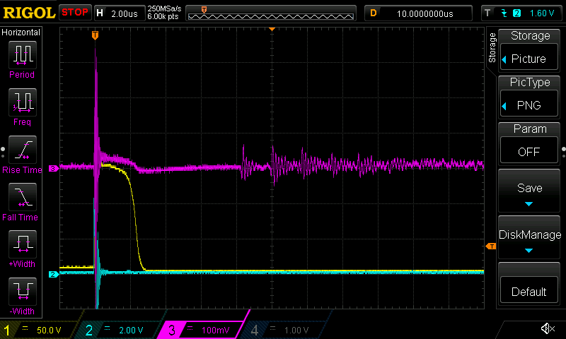
I am developing an ultrasonic sensor for NDT testing, specifically with the goal of measuring the thickness of metal.  I am using a 5MHz dual-element probe (Yushi PT-08A, Link).  I will attach the response signal I see with just my 10M/13pF scope probe loading the signal, for reference the signal is about 100mV peak-to-peak and has high-frequency components of about 10MHz. Note I'm planning to use a fast ADC with >20MSPS to read the signal, which accepts input signals up to 1Vp-p and has input bias current of 3uA (specifically we're testing with LTC8365 for now, however if you have a suggestion here we would be open to using a TI ADC).

From my research, most designs here use an LNA followed by a VGA.  I'm not quite sure if these need to be separate and am hoping you would help me select appropriate part(s).  I think the most important specs are low noise (e.g. <1nV/sqrt(Hz)), low input bias current (<10pA), and high bandwidth (>20MHz at least, although with gain perhaps >200MHz).  We want to operate off a single 3.3V rail.

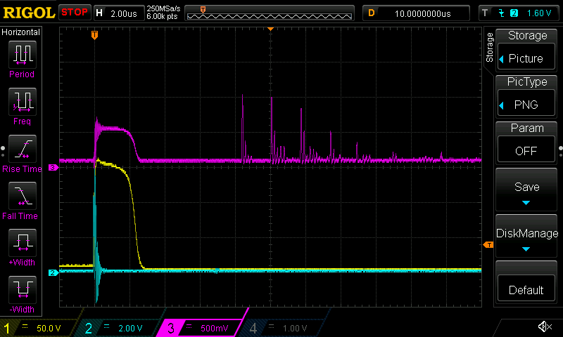
So far, the best results I've gotten are with an OPA356 setup as a non-inverting amp with 1k and 50 ohm resistors in the network (giving gain of 20).  I don't quite understand what happens to the signal, but I very much like the result as it clearly separates the rings.  I do note that the noise figure is a bit higher than 1nV/sqrt(Hz), however still fairly low.  Also this is just a normal op-amp so the gain would be set via hardware resistor values which is okay, although having it be programmable may be a nice feature.

Can you help suggest part(s) we should use?  Would we benefit from separating to two separate amps, or as long as we meet our specs and don't need much gain are we okay with a single amp?  I'm not clear on how the voltage noise (nV/sqrt(Hz) would be affected when using two amps (e.g. do the figures add, multiply, or does only the first amp's noise figure count)?

I appreciate any insight you may have.

Kind Regards,
-Jon

  • Hi Jon,

    simplified spoken:

    When the gain of the first stage is high compared to the gain of the second stage, then only the noise of the first stage counts. This has to do with the fact that noise is added geometrically, but not arithmetically:

    Let's have an example. If two noise signals are to be added and the dominant is three times higher, then the noise sum is not:

    1 + 1/3 = 1.333  (arithmetically)

    but:

    SQRT (1^2 + (1/3)^2) = 1.05  (geometrically)

    So, the total noise is only increasing by 5%.

    The higher the gain of the first stage, the less the noise of the second stage is contributing to the overall noise Relaxed

    Kai

  • Thank you Kai.  I understand if gain is being used in the first amp the noise will not be as significant in the second amp.  However if gain is being performed in first amp, why would a second amp be necessary?

    Do you have any suggestion for what part(s) I should consider using? 

  • Morning Jon, 

    A lot of times we are using a higher input impedance 1st stage with gain and low noise then into an FDA for maybe more gain and filtering to control integrated noise up to the ADC (where most ADC's are diff input, so the FDA takes care of that).

    For 3.3V operation, for the lowest input noise use a decomp VFA device - the OPA838 is bipolar, for MOS input there is an LMP7718. Then if you need a diff drive to the ADC (and MFB filtering is easy to add to that), a 3.3V FDA might be the THS4551. 

  • Hi Jon,

    because of bandwidth issues. The OPAmp should provide some gain reserve at the highest frequency of interest to have enough linearizing feedback. That's how an OPAmp is intended to work.

    Let's have an example:

    Assume you want 60dB gain at 1MHz. Then you need an OPAmp with a minimum bandwidth of 1GHz. But even with this high bandwidth you still don't have any gain reserve at 1MHz. For a gain reserve of 40dB you would need an OPAmp with a bandwidth of 100GHz Scream

    What to do?

    You split the total gain onto several individual OPAmps. Taking three OPAmps in a row each providing a gain of 20dB, the OPAmps would need a bandwidth of 1GHz each.

    Kai

  • Hi Jon,

    In addition to Kai's reply:

    Ideally, yes, you can use single opamp with ultra-high gain-bandwidth product and extremely low noise to build your circuit. But in reality, you don't have such opamps. There's always tradeoff between the two. Even though you find such a part, it may come at price of cost, size and power consumption.

    How to solve this? As Kai's and Micheal's suggestion, you split your signal chian into two or multiple stages. In the 1st stage, you choose an opamp with lowest possible noise and enough bandwidth. In the 2nd (and the following, if there is any) stages, you can provide the required gain. In such way, you can have a low cost, low noise and high speed signal chain.

    Furthermore, if the bandwidth of your signal is 10MHz, the closed-loop bandwidth of the opamp and the analog bandwidth of ADC are recommeded to be greater than 50MHz, otherwise you may have appreciable distortion at 10MHz. If you will perform FFT signal processing, higher sampling rate is recommended since this will result in higher SNR.

    As for programmable gain, if you don't want to use VGA, you may try a digital potential meter in your feedback loop. I'm not sure of this. Let's waiting for Kai's and Mecheal's comments.

    Yubing

  • Hello Jon,

      I just wanted to add on top of everyone else's great inputs that here is a list with higher GBW amplifiers with slightly higher input voltage noise compared to the OPA356. These amplifiers could be a good substitution if you need to go higher BW due to a need for higher gain. As everyone else noted, you do not necessarily need a 2nd stage unless you need a higher overall gain that exceed OPA356's GBW, but do not want to increase voltage noise by replacing the OPA356 with these higher GBW amplifiers. As Michael mentioned, you could have a FDA in multiple feedback lowpass filer (MFB). This will cut down on the noise and distortion and works well as an interface with an ADC. I could not find the LTC8365 online, would you be able to share the datasheet for this device?

    Thank you,

    Sima 

  • Thank you Michael.  I am concerned about the limited slew rate of LMP7718; if I'm targeting a 1Vp-p output, the 11.5V/us would limit transitions to 87ns (11.5MHz). 

    Regarding the VFA, this is interesting.  The ADC dev board I'm using has an analog input network including a transformer to make a single ended input differential (see pg 6 of datasheet https://www.analog.com/media/en/technical-documentation/user-guides/dc782a.pdf).  I was planning to copy this into my design, however if you think a VFA would bring improvements I'm interested to learn more.

  • Thank you Kai.  I understand what you're saying here, but I am only looking for ~21x gain, which is less than 15dB.  Would you recommend I still consider 40dB of overhead?  This seems like overkill, although I do realize I've got zero overhead with OPA356 setup for 21x gain and signal up to 10MHz (GBWP = 210MHz, while OPA356 is only 200MHz).  Yubing mentioned a 5x overhead, which seems much more reasonable than 40db overhead (4096x overhead!)

  • SimaJalaleddine, I apologize I mentioned the wrong part.  The part is actually LTC2248, dev board DC782A-M (here's the datasheet: DC782A-M)

  • Hi Jon,

    the 40dB headroom was only an example. 40dB makes sense in an audio application or where very little gain drift, distortion, etc. is mandatory. In your application less headroom may still be acceptable, I guess.

    But having no headroom at all is definitely no good idea. Keep in mind that you have not only the 5MHz fundamental in your signal but -due to the switchings- very far reaching harmonics. So if you still want to use the OPA356, I would split the gain of factor 21 onto two OPA365, one with gain factor 5 and the other with gain factor 4...5.

    Another issue: What are you doing with the negative going half waves at the input of OPA365? I ask because leaving the common mode input voltage range could slow down the OPA365 and leaving the absolute maximum input voltage range could damage the part.

    Kai

  • Hello Mr. Schweiger, 

    The dev board will often have just a balun input to get very good SFDR measurements. However, you do give up DC coupling if you go that way which is one main reason FDA's are so popular. 

  • Thank you Kai, I understand your reasoning here and agree headroom is a good idea.  Would it be better to use something like LMH6703 rather than 2xOPA365?  I see the LMH6703 has much higher GBW at 1800MHz and lower noise at 2.3nV/rtHz so seems like I'd have more overhead and a simpler solution.  Again, I'm totally open to what amp I use and suggestion of a component is really the core reason for this support request.

    Regarding harmonics, I was planning to use a LPF in the feedback network of the LNA, and perhaps an additional LPF or bandpass stage before the ADC.

    I wasn't clear on the other issue you mentioned about negative portion of waves.  Can you elaborate and/or provide your suggestion for avoiding this concern?

    -Jon

  • Hi Jon,

    the minimum suppy voltage of LMH6703 would be +/-4V which was not suited for your desired single 3.3V rail.

    Kai

  • Hello Jon,

    Sorry, did not mean to mark this post as resolved; please ignore that notification. Would the OPA859 work? It fits the 3.3V single supply rail, lower noise at 3.3nV/rtHz, and higher BW/slew rate. Also, thanks for the ADC datasheet; I will have to discuss with the ADC group for that device.

    Thank you,

    Sima

  • Hi Jon,

    the negative going pink pulse can kill the OPAmp without input current limiting:

    Kai

  • Thank you Kai.  You are correct that LMH6703 does not meet the voltage spec per my original request, however if moving to a 5V single supply opens up better options I would be open to this.

    I also appreciate your clarification on the negative going pulse.  That capture in question was the receiving element hooked directly to my 10M/13pF scope with no circuitry.  I don't believe that spike is actually there; I believe it is an artifact from the 150V pulse at Channel 1, perhaps improper grounding of the probes.  That said, I appreciate your caution and will do my best to keep the signal within Vcm and also ensure we limit current for absolute max voltage.

  • Thank you Sima for suggesting the OPA859.  I looked at this part as well as the OPA858 however I was concerned that they were really meant as trans impedance amplifiers.  Is this part reasonable to use with a voltage pulse source as we have here?

  • Hello Jon,

       The OPA858 is marketed as an amplifier for transimpedance designs, but can be used as a regular voltage feedback amplifier. Would you be able to share your schematic either here or if not offline by using a private chat?

    Thank you,

    Sima

  • Hi Jon,

    if the OPA365 satisfies your needs then go for the OPA365.

    But I would add some current limiting resistor at the input to protect the OPAmp. Eventually, in combination with a diode clamp. The 150V actuation signal is so high that even with very little stray capacitance the OPAmp could be in danger.

    Kai

  • Thank you Sima.  My plan was a basic non-inverting op-amp with AC coupled input.  I'm also planning an in-series resistor per Kai's suggestion to ensure current is limited.  Here is the circuit:

  • Thank you Kai.  I will ensure I use a current limiting resistor of at least 10 ohms to ensure our 100mV signal does not produce more than 10mA current.  I plan to use 1k to have plenty of margin which shouldn't be a big deal thanks to the low input current.  Note that the 150V actuation is on a separate transducer so there isn't risk of that voltage appearing. 

    I am still thinking the OPA365 doesn't provide any overhead as we are looking for 21x gain at up to 10MHz.  It sounds like your suggestion is 2xOPA365, each with gain around 4.5x (allowing overhead of 45MHz vs 200MHz).  This is okay, although we have mentioned some parts with over 1GHz bandwidth which allows more overhead and solution in one chip.  I'm interested in your thought on OPA858.

  • Hi Jon,

    it heavily depends on your application how much overhead you need. It's a difference whether you just want to detect the begin of an echo or if you want to reproduce the echo with 0.001% distortion Relaxed

    Kai 

  • Hello Jon,

      Were you able to continue with the OPA356? It looks like another advantage with the OPA356 is that it is rail to rail, with the OPA858 you will face clamping at the negative supply of 1.05V with an input signal of 100mV and gain of 20. 

    Thank you,

    Sima