This thread has been locked.

If you have a related question, please click the "Ask a related question" button in the top right corner. The newly created question will be automatically linked to this question.

Super High Speed Peak Detector Needed

Other Parts Discussed in Thread: BUF602, OPA615, TL054

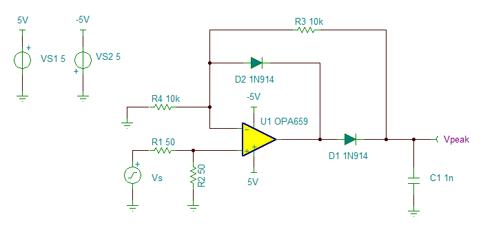
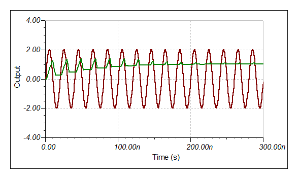
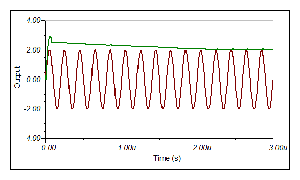
I need a super high speed peak detector, able to accurately peak detect a 10ns to 20ns pulse. Is there such an animal, what is the schematic and what amplifier should I use? I see a TI app note sbos138 with a BB 3507J amplifier but the circuit may not be fast enough and apparently the 3507J is no longer available.

Any help please?

Thanks,

John

  • John,

    There are a couple ways to peak detect a high speed signal. 10ns-20ns puts you in the 50MHz-100MHz range, so you need high BW and fast slew rate. You also need an amplifier that can handle driving large capacitive loads and can settle relatively quickly (<10ns).

    The most basic peak detector configuration is to use a single op amp with a diode in the feedback path and a diode at the output like in the configuration below. The main drawback of this approach is that you will be limited on speed and wouldn't be able to reach the 10-20ns you're looking for. Also note, that there will be two diode drops so your peak voltage will Vpeak - (2* VD) which may or may not be a concern depending on the amplitude of the input signal.

    In order to reach higher speeds, you could use the OPA615 and BUF602 in the configuration shown on figure 48 of the OPA615 datasheet. This device has a built in OTA to source additional current and help reduce the rise and fall times of the amplifier. This allows the amplifier to more quickly charge the sampling capacitor its peak value, enabling sampling times in the ns range. In addition, there is sample and hold circuitry included in the amplifier which would allow you to tune the sampling rate of the amplifier. This configuration would also enable you to detect negative peaks as well as positive peaks by adding the BUF602 circuitry. Overall, this appears to be a very good option for high speed peak detection.

    Regards,
    Luke Lapointe
    High Speed Amplifiers

  • Thanks very much Luke. This looks very promising and also I see that an eval board is available for the opa615, so I can try it out. Great help, thanks again!

    BTW, I found an EDN article using a Maxim MAX9690 comparator that looks promising too but Maxim doesn't have any info about such a circuit and also they say they don't have an eval board for the part: http://www.edn.com/file/18037-92602di.pdf

    John

  • Luke:

    In retrospect, after more carefully reading your note, I see the output voltage "there will be two diode drops so your peak voltage will Vpeak - (2* VD)" so that may be a problem since my input voltage peak will be only 1V.

  • John,

    In order to detect 1V peaks as you describe, you can amplify the signal before the peak detecting stage. This will give you a little more margin for the diode drops and still maintain the signal. The downside is that increasing the gain too much will cause the signal to clip and too little gain will not forward bias the diodes to let the signal get through. You will have to decide what the minimum detectable peak is for your design and set your gain accordingly. You can also use Shottky diodes with a 0.4V drop each to help mitigate this effect.

    Regards,
    Luke Lapointe
    High Speed Amplifiers

  • Luke:

    I am suspicious that your assertion about the 2 diode drops is incorrect. I haven't yet run a SPICE program on the circuit but my reasoning is as follows. If for example, the input voltage to the resistor divider is 2V, the divider would cut it in half to 1V. Then since the opamp would drive the output until the voltage at the negative (-) opamp input is the same as at the positive input, or 1V, then the current to ground thru R4 will be 0.1mA and also the current thru R3 will be 0.1mA, resulting in 2V at the opamp output since no current enters or exits the negative input to the opamp. Thus, no 2-diode voltage drop.

  • Luke:

    I analyzed a peak detector circuit using MicroCap 8 and don't see any 2 diode drop. The circuit is not optimized for high speed but just a test of the idea. Circuit is not fast enough and getting too much droop. But it looks promising.

    Thanks,

    John

    4341.PeakDetectorOpAmp.pdf

  • John,

    It appears as though you are correct. When simulating, the frequency as well as capacitance value will determine what value the output will settle too as well as how much droop is present. I ran the same circuit with 50MHz and 5MHz. See results below.

    Let me know if you have any further questions.

    Regards,
    Luke Lapointe
    High Speed Amplifiers

  • Much thanks Luke. It looks like the OPA615 will do the job for me. I can adjust the cap on the Hold_CTRL output for overshoot, depending on the pulse width, so should work great. I have recvd a couple of eval boards and have some OPA615 SO14's on order. Attached is a pdf of my simulation of the circuit with Microcap 8.

    Thanks again,

    John

    8272.PeakDetectorOPA615.pdf

  • Whoops! I meant I can adjust the cap after the diode to set the overshoot, depending on the pulse width.

  • Hi John

    Can you please load the microcap file, i want to open it using microcap

    thanks

  • Good day

    In the attached circuit, i use OPA615 to detect nanosecond peak pulses,i am trying to reset the chip through a charge and discharge capacitor Chold

    so that my circuit can be reset to zero after every pulse detection,i am asking for assistance on this

    Regards

    Nico

    3146.reset.TSC

  • Nico:

    Sorry I missed your request for my Microcap file. Do you still want it?

    Can you submit a pdf of your design?

    John

  • Nico:

    I suspect the capacitance of the IRF530 might be too large and it might be too slow but I haven't tried analyzing the circuit. I didn't reset the OPA615 directly, but had a following circuit with a TL054 and reset the cap on it.

    John

  • The circuit is eaxactly like the one in the attached pdf.i want to reset it everytime before each pulses so i dnt miss shorter pulses

    i tried to change the capacitor value to different values with no sucess, and no thanks i wnt use the microcap anymore.

    0676.microcap forum circuit.PeakDetectorOPA615.pdf

    Nico

  • Nico:

    Your Tina schematic shows an IRF530 across the C1 cap. The IRF530 output capacitance is nominally 250pF, so would be swamping C1, slowing the peak detector circuit response and also the IRF530 is probably very slow at discharging C1. See http://www.vishay.com/docs/91019/91019.pdf.

    John

  • Hi John

    Thanks i will consider that

    Regards

    Nico

  • Hi John

    on the same circuit, im trying to create an input signal of different pulse widths on the signal editor function

    the following is what i have for 10ns,do you think this is correct, i also want to use 100ns,100us and 1ms

    * Pulse of varying amplitude
    + 2.2u 0

    + 0.005u 1
    + 0.005u 1
    + 0.1u 0

    + 20u 0
    + 0.005u 3
    + 0.005u 3
    + 0.1u 0

    + 20u 0
    + 0.005u 2
    + 0.005u 2
    + 0.01u 0

    + 20u 0
    + 0.005u 3
    + 0.005u 3
    + 0.01u 0

    Thanks in Advance

    Nico

  • Hi Nico:

    Sorry but I don't know what you mean.

    John

  • Hi John

    sorry i couldnt get back to you on the previous question but i ended up coming right

    I am now simulating the circuit on page 20 figure 47.'Integrator fo ns-Pulses'

    the circuit is supposed to intergrate an input pulse of about 100ns, and the results i get are oscillations as depicted in the picture bellow

    i dnt beleive this to be the correct result,how can i overcome this osccilations?

    Thanks

    Nico

  • Is it possible for you to upload the multisim simulation file or the OPA 615 model in multisim. I am unable to make the model in Multisim.

    Regards
    Keyur Mistry