This thread has been locked.

If you have a related question, please click the "Ask a related question" button in the top right corner. The newly created question will be automatically linked to this question.

TRF37A73EVM: TRF37D73 / about TRF37x73 EVM schematic design

Part Number: TRF37A73EVM
Other Parts Discussed in Thread: TRF37A73

Hi,

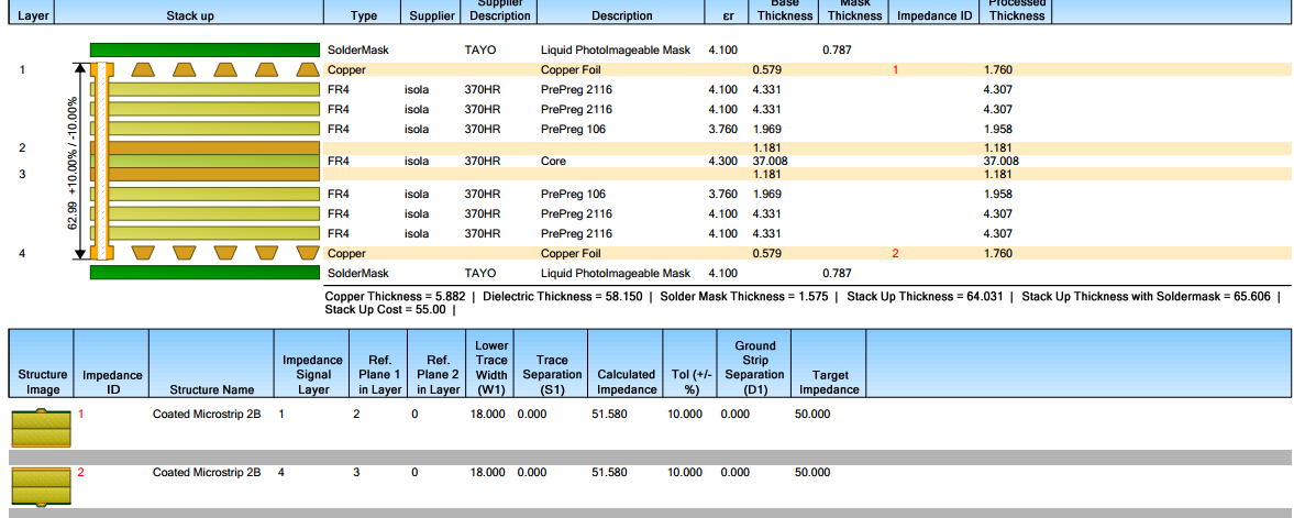
I'm planning to design amplifier gain  PCB using TRF37X73 (X= A or B or C or D) and i'm planning to use following stack-up is it suitable ?? If not can you please suggest me stack-up for designing this PCB...
  • Hi Deepthi,

    I think the stack-up looks ok for designing the TRF37X73 PCB.

    Best Regards,

    Rohit

  • Hi,

      I'm planning to use BNX016-01 EMI/EMC filter for power supply, What are special caring's  to be taken to qualify this PCB in EMI / EMC qualification and Can you suggest me Best stack up for this PCB to qualify EMI / EMC qualification.....

  • Hi Deepthi,

    As long as there are no spurious emissions from the device/pcb or is within the EMI/EMC regulatory requirements of the specific country, I think the PCB should be able to qualify the EMI/EMC test. This certainly includes any self-oscillatory conditions of the part. Using an EMI/EMC filter on the power supply certainly helps, along with the right power supply bypass capacitors.

    I think the stack-up you have is similar to the TRF37A73 EVM, so should be ok. You might want to take a look at the RF regulatory compliance page of the user's guide: www.ti.com/.../slau546.pdf to know what compliance tests does the EVM qualify for.

    Best Regards,
    Rohit