This thread has been locked.

If you have a related question, please click the "Ask a related question" button in the top right corner. The newly created question will be automatically linked to this question.

THS4631: Ask problems about loop gain caiculations for op amp system

Part Number: THS4631
Other Parts Discussed in Thread: TINA-TI, , THS3062

Dear TI expert,

I have some problems about loop gain calculations of op amps by TINA-TI.

1.I see this slide Fig1(the resolution is poor) in that video on the website

training.ti.com/ti-precision-labs-op-amps-stability-3. They all break the loop from the op amp’s output. And I wonder what are the right ways to measure the loop gain for CFA? 
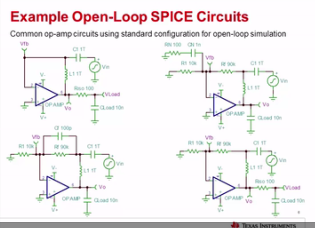
Fig1

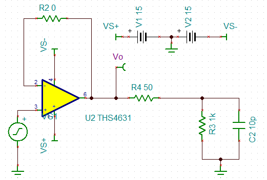
2.Fig2 is from THS4631’s datasheet(pp5/34, Figure6). I test the closed-loop transfer function under Fig2’s condition. And I find that with an isolation resistance 10ohms, the closed-loop transfer function will have no peaking even with 100nF load capacitor. Can you please show me the correct result or just offer me the correct simulation circuits for this?
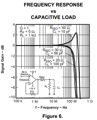
Fig2

3.I want to implement analog proportion-integration regulator with high speed op amp. If I choose VFA, its gain bandwidth product will be 350MHz, and supply voltage are greater than ±15V.For the sake of performance, what do you recommend? VFA or CFA, which is better for this application?


Best regards!

Yatao

  • Hi Yatao,

    1. There is another precision labs video explaining the loop gain of CFAs found here. training.ti.com/ti-precision-labs-op-amps-current-feedback-amplifiers-overview-and-compensation-techniques
    2. As you can see from Figure 6, increasing Cload does decrease peaking. The Riso and Cload start to act as an RC low pass filter. The precision labs videos on CFAs should improve your understanding.
    3. Based on the easier design of an integrator using a VFA, that is what I would recommend. However, it is really a matter of preference, as it is possible to use either type of amplifier.

    Best regards,

    Sean
  • Dear Sean,

    Thank you for your reply.

    1.I’ve watched the video, and I guess that you mean the methods to simulate the loop gain by TINA-TI from on-line video (https://training.ti.com/ti-precision-labs-op-amps-stability-3?cu=14685) apply also for CFA?

    2.I’ve simulated under the conditions in Fig6(from THS4631’s datasheet, pp5/34) and Fig1 shows my TIAN-TI simulation circuits. But the simulation results are very different from the datasheet’s result. For example, when RISO=50ohms, CL=10pF, the AC transfer function by my simulation file is as Fig2 below(gain and phase characeristics are form top to bottom). After my measurements of Fig2, there are technically no AC peaking, which is observed in datasheet’s Fig6, pp5/34. This problem bothers me for 2 days and I have no choice but ask you for help. Please check my simulation circuit and tell me the right results. Thank you very much!

    Fig1 TINA-TI simulation circuit for driving capacitance load

    Fig2. Simulation results

    3.You say that “Based on the easier design of an integrator using a VFA”. And can you give more details about what are the aspects where VFA and CFA differ from each other when implemented as an integrator? Thank you very much!

    4. Does TI have high-speed op amp, with supply voltages greater than ±15V and GBP(Gain-Bandwidth Product) greater than 350MHz? I’ve searched but found none.


    Best regards!

    Yatao

  • Hi Yatao,

    1. The stability analysis for CFAs is different. The stability is determined by the value of the feedback resistance, as described in the CFA videos.
    2. The simulation models are not perfect, and you should defer to the datasheet for capacitive load drive, since it is measured using an actual device.
    3. The difference is the type of circuit that must be used, since you cannot put a capacitor in parallel with the feedback network. You can use the topographies of the THS3062 Figures 56 and 57.
    4. We do not have such an op amp.

    For additional questions, please start another thread.

    Best regards,

    Sean