This thread has been locked.

If you have a related question, please click the "Ask a related question" button in the top right corner. The newly created question will be automatically linked to this question.

How to maintain stability of a TIA when exceeding the open loop gain

What is the open loop gain limit that I must stay below for stability when making a transimpedance amplifier with an op amp? Why am I allowed to exceed the open loop gain? Why does the gain limit of a transimpedance amp roll off at more than 20dB/decade?

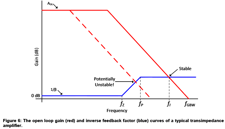
I am trying to make a transimpledance amplifier for a photodiode. For stability, the gain of an op amp must intersect the open loop gain of the op amp at a 20dB/decade angle. Here's a graph from TI's document # TIDU535 that illustrates this point:

This document is contradictory in a way. The example in figure 10 (in the doc TIDU535) uses a feedback resistor of 53.6KΩ for a gain of 94.6dB. The circuit gets a -3dB roll off at 1.464MHz. The op amp has an open loop gain (Aol) of ~130dB and a GBW of 20MHz.  This op amp should roll off at 373Hz due to the limits of the GBW and Aol.

Thomas Kuehl address this concern here: https://e2e.ti.com/support/amplifiers/precision_amplifiers/f/14/p/379953/1338396#1338396
He essentially says you can exceed Aol because Aol only applies to amplifying volts to volts. A transimpedance amplifier is amplifying current to voltage so Aol can be exceeded. Unfortunatly, he doesn't explain why Aol can be exceeded, only that it is.

There is a limit according to simulation. This simple setup in TI-TINA shows that I can get 120dB of gain at 5.8MHz out of an op amp with an Aol of 110dB and a GBW of 100MHz. The other confusing thing is that the rolloff is ~46dB/decade instead of the normal 20dB/decade we see when amplifying volts to volts.

What is the open loop gain limit that I must stay below for stability when making a transimpedance amplifier with an op amp? Why am I allowed to exceed the open loop gain? Why does the gain limit of a transimpedance amp roll off at more than 20dB/decade?

TI has done an amazing job of providing resources that hold your hand through the design of this circuit, but I need to know why/how it achieves the gain it does despite Aol limits, and more importantly how to ensure my circuit is stable.

  • Hello,

    Thomas explained this in pretty great detail in the post linked at the bottom of this message, but stability and loop analysis can be a little tricky so I'll try to explain it again as well.  I also suggest that you go through the TI Precision Labs videos on op amp stability.  I think you'll enjoy the videos as they discuss the basics of op amp stability including open-loop gain (Aol), the feedback factor, beta (B) loop-gain (Aol*B) along with the other basics of feedback and stability analysis.  The differences between signal-gain, which is gain your input signal sees, versus the circuit noise-gain, which is the non-inverting gain of the op amp, are also discussed.  The noise gain determines the gain the input noise is amplified by as well as the stability of the circuit.

    To answer your original question, the gain you're measuring is the current-to-voltage gain of the circuit which is simply the resistance of the 1M feedback resistor.  This is based on Ohm's Law : R = V/I.  That's why you're seeing 120dB, or 1MV/A, gain from the current input to the voltage output.  However, this does not mean that you're exceeding the open-loop gain of the amplifier which is determined based on the change in output voltage versus the change in input offset voltage (V/V). 

    As shown in the blog you referenced, the noise-gain of a transimpedance circuit is unity-gain (0dB) at low frequencies and eventually increases due to the zero formed by the interaction of the input capacitance of the amplifier and sensor and the large feedback resistor.  This is why a feedback capacitor is required in parallel to the feedback resistor.  The feedback capacitor interacts with the feedback resistor to form a pole that cancels the zero from the input capacitance.  I suggest you employ the methods discussed in the TI Precision Labs videos to simulate the loop-gain curves for your circuit to understand what makes the circuit unstable as well as how to stabilize it.  For a quick fix to your circuit stability troubles try placing a 1pF capacitor in parallel with your 1M resistor.  This will limit your circuit bandwidth to 159kHz.  If you need higher bandwidths you'll have to use a smaller feedback capacitor and/or resistor.


  • One of my colleagues suggested a simpler way to observe the voltage gain of this circuit.  The first image displays a transimpedance circuit with a photodiode input.  The photodiode is represented by a current source and a shunt impedance.  The shunt impedance of a photodiode is typically extremely large and is 100GOhms in the circuit below.

    If a source transformation is used to convert the current source (Iin) and shunt resistance (R1) to a voltage source (Vin) with series impedance (R1), the circuit in the image below is the result.  In this case the circuit appears as a standard inverting amplifier with gain of Vout/Vin = -R2/R1.  The circuit noise-gain (non-inverting gain is equal to 1+R2/R1.  Using the values shown this results in an inverting voltage gain of -1M/100G = 10uV/V and a non-inverting gain of 1.00001 V/V ~(1V/V).  This is why the dc noise-gain of a transimpedance circuit is effectively 0dB or 1V/V.

  • This makes perfect sense. The photodiode and op amp have some capacitance impedance that looks smaller as you increase in frequency; hence the increasing gain with frequency that must be countered by a pole in the feedback loop. Thank you.